Vivotek IP7361 Quick Installation Manual
Network camera outdoor 2mp
Hide thumbs
Also See for IP7361:
- Specification (2 pages) ,
- User manual (170 pages) ,
- Quick installation manual (13 pages)
Table of Contents
Advertisement
Quick Links
Advertisement
Table of Contents

Subscribe to Our Youtube Channel
Related Manuals for Vivotek IP7361


Summary of Contents for Vivotek IP7361
- Page 2 Warning Before Installation Power off the Network Camera as Refer to your user's manual for the soon as smoke or unusual odors are operating temperature. detected. Contact your distributor in the event of occurrence. Do not touch the Network Camera Do not place the Network Camera on during a lightning storm.
-
Page 3: Package Contents
Package Contents IP7361 with an RJ45 Cable Sun Shield RJ45 Waterproof Connector for RJ45 Wall Mount Bracket Ethernet Enclosure Alignment Sticker / Silica Gel Power Adapter Software CD Waterproof Connector (for backup use) Quick Installation Guide Warranty Card EN-2... -
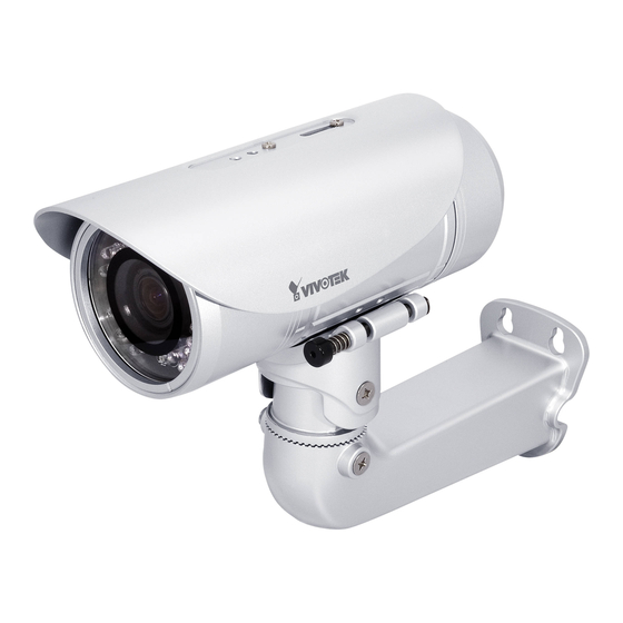
Page 4: Physical Description
Physical Description Lens IR LED Light Sensor SD/SDHC Card Slot General I/O Reset Button Terminal Block Status LED Power Cord Socket RJ45 Cable EN-3... -
Page 5: Hardware Installation
Hardware Installation 1. Attach the alignment sticker to the wall. Drill four holes into the wall. Then hammer the supplied plastic anchors into the holes and secure the plate with supplied screws. 2. Fix the -bracket to the side of the Network Camera with two screws. 3. -
Page 6: Waterproof Connector
Waterproof Connector Components of the Waterproof Connector Pin Definition Power +12V Digital Output Screw Nut (A) Digital Input Seal (B) Ground AC 24V Seals (C) AC 24V Housing (D) RS485 + Sealing Nut (E) RS485 - External MIC In 4 3 2 1 Ground Audio Out Ground... -
Page 7: Cabling Assembly
Cabling Assembly RJ45 Cable Connector RJ45 Cable Dimension (unit: mm) Components of the Waterproof Connector Sealing Nut (A) Seal (B) Screw Nut (C) Housing (D) Gasket (E) Assembling Steps Insert the seal into the housing. Insert the housing into the Prepare an Ethernet cable screw nut. -
Page 8: Network Deployment
Network Deployment Power over Ethernet (PoE) When using a PoE-enabled switch The Network Camera is PoE-compliant, allowing transmission of power and data via a single Ethernet cable. Follow the below illustration to connect the Network Camera to a PoE-enabled switch via Ethernet cable. PoE Switch When using a non-PoE switch Use a PoE power injector (optional) to connect between the Network Camera and a non-PoE... -
Page 9: Assigning An Ip Address
"Next" button to continue the program. Installation Wizard 2 3. The program will search for VIVOTEK Video Receivers, Video Servers, and Network Cameras on the same LAN. 4. After searching, the main installer window will pop up. Click on the MAC that matches the one labeled on the side of the camera or S/N number on the label of carton to connect the Internet Explorer to the Network Camera. -
Page 10: Ready To Use
Ready to Use 1. Access the Network Camera from the LAN. 2. Retrieve live video through a web browser or recording software. For further setup, please refer to the user's manual on the software CD. 3. Unscrew the zoom controller to adjust the zoom factor. - Page 11 5. Tighten the lens cover. 6. Open the back cover. 7. Tear down the aluminum foil vacuum bag and take out the silica gel. Attach the silica gel to the inner side of the back cover, then tighten the back cover. (Please replace the silica gel with a new one if you open the back cover after installation.) Note If you want to use the supplied sun shield for outdoor environments, please follow the steps below to...
- Page 12 Accessories VIVOTEK also provides other accessories for versatile applications as the following illustrations. Please visit VIVOTEK's official website for more purchase information. Pole Mount Bracket Pendant Mount Bracket Corner Mount Bracket IR illuminator (distance 30m, 60°) Built-in 20 LED units (distance 25m, 35°)
- Page 13 NOTES Quick Installation Guide EN-12...
Need help?
Do you have a question about the IP7361 and is the answer not in the manual?
Questions and answers