HAUL MASTER Trailer 94564 Assembly And Operating Instructions Manual
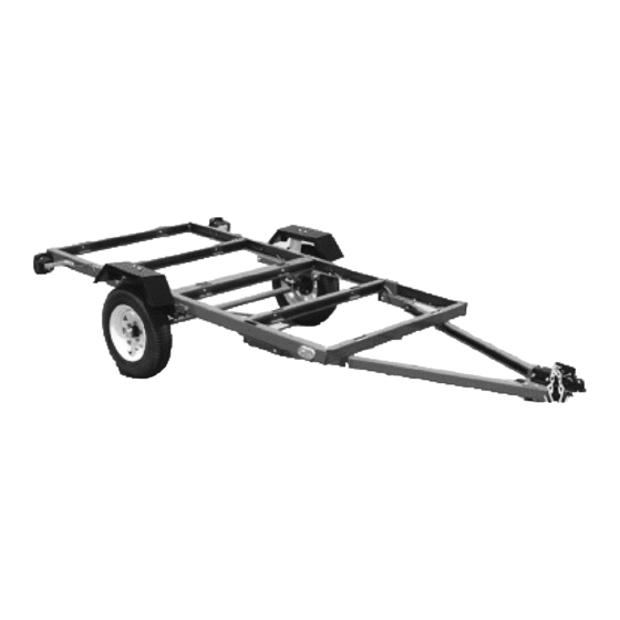
4' x 8' trailer
Hide thumbs
Also See for Trailer 94564:
- Assembly and operating instructions manual (27 pages) ,
- Assembly and operating instructions manual (27 pages)
Table of Contents
Advertisement
ASSEMBLY AND OPERATING INSTRUCTIONS
This trailer's Hitch Coupler MUST be properly secured to the hitch ball of the towing vehicle. After assembly and
attachment, pull up and down on the Hitch Coupler to make sure the hitch ball is fitting snugly in the Hitch Coupler.
There must be no play between the hitch ball and Hitch Coupler. If there is play, tighten the Adjustment Nut
until no play is present. If the Adjustment Nut is too tight, the Handle will not lock. Carefully read and follow the
complete instructions in this manual BEFORE setup or use.
If the Coupler is not secured properly, the ball could come loose while the trailer is in motion, possibly caus-
ing property damage, SERIOUS PERSONAL INJURY, or DEATH.
Visit our website at: http://www.harborfreight.com
Read this material before using this product.
Failure to do so can result in serious injury.
SAVE THIS MANUAL.
Copyright
©
manual or any artwork contained herein may be reproduced in any shape or form
without the express written consent of Harbor Freight Tools. Diagrams within this
manual may not be drawn proportionally. Due to continuing improvements, actual
product may differ slightly from the product described herein. Tools required for
assembly and service may not be included.
For technical questions or replacement parts, please call 1-800-444-3353.
Revised Manual 10d
TRAILER
Model
IMPORTANT INFORMATION
2006 by Harbor Freight Tools
4' x 8'
94564
WARNING!
. All rights reserved. No portion of this
®
Advertisement
Table of Contents

Related Manuals for HAUL MASTER Trailer 94564


Summary of Contents for HAUL MASTER Trailer 94564
- Page 1 © manual or any artwork contained herein may be reproduced in any shape or form without the express written consent of Harbor Freight Tools. Diagrams within this manual may not be drawn proportionally. Due to continuing improvements, actual product may differ slightly from the product described herein. Tools required for assembly and service may not be included.
-
Page 2: Table Of Contents
SPECIFICATIONS ... 3 UNPACKING ... 3 GENERAL SAFETY RULES ... 3 Work Area ...3 Equipment Use and Care...4 Service ...5 SPECIFIC PRODUCT WARNINGS AND PRECAUTIONS ... 5 ASSEMBLY INSTRUCTIONS ... 7 Phase 1: ...7 Phase 2: ...8 Phase 3: ...9 Phase 4: ...9 Phase 5: ...10 Phase 6: ...10... -
Page 3: Specifications
Maximum Payload Capacity Bed Dimensions Required Hitch Ball Size (not included) Wheel Rim Diameter & Width Tire Size & Type Wheel Lug Nut Quantity & Torque Requirement Required Tire Air Pressure Stop & Tail Light Type Side Running Light Type Ground Clearance Overall Dimensions Ship Weight / Net Weight... -
Page 4: Equipment Use And Care
Replacement parts and accessories: When servicing, use only identical replace- ment parts. Only use accessories intended for use with this product. Approved accessories are available from Harbor Freight Tools. Maintain this product with care. Keep this product clean and dry for better and safer performance. -
Page 5: Service
Equipment service must be performed only by qualified repair personnel. Service or maintenance performed by unqualified personnel could result in a risk of injury. When servicing equipment, use only identical replacement parts. Follow instruc- tions in the “Inspection, Maintenance, and Cleaning” section of this manual. Use of unauthorized parts or failure to follow maintenance instructions may create a risk of personal injury. - Page 6 However, NHTSA can not become involved in individual problems between you, Harbor Freight Tools, or the manufacturer. To contact NHTSA, you may either call the Auto Safety Hotline toll- free at 1-800-424-9393 or 202-366-0123 or write NHTSA, U.S.
-
Page 7: Assembly Instructions
ASSEMBLY INSTRUCTIONS Phase 1: Parts Needed Part # Description Qty. Front Left Side Rail Front Right Side Rail Cross Member Cross Member M10 x 20 Bolt M10 Nylon Nut FRONT END OF TRAILER Lay out the Front Left Side Rail (1FL), Front Right Side Rail (1FR), one Cross Mem- ber (2A), and two Cross Members (2B). -
Page 8: Phase 2
Phase 2: Parts Needed Part # Description Qty. Left Connecting Rail Right Connecting Rail Angle Iron T-Plate Coupler Base L-Latch M10 x 20 Bolt M10 x 25 Bolt M14 x 30 Bolt M10 Nylon Nut M14 Nylon Nut 3mm R-Pin Attach an Angle Iron (4) to the Front Left and Front Right Side Rails (1FL, 1FR) and Cross Member (2B), using the M10 x 20 Bolts (A) and M10 Nylon Nuts (I). -
Page 9: Phase 3
Phase 3: Parts Needed Part # Description Qty. Rear Left Side Rail Rear Right Side Rail Cross Member M10 x 20 Bolt M10 Nylon Nut Lay out the Rear Left Side Rail (1RL), Rear Right Side Rail (1RR), and three Cross Members (2B). -
Page 10: Phase 5
Phase 5: With assistance, turn the frame upside down. Parts Needed Part # Description Left Spring Hanger Right Spring Hanger M10 x 25 Bolt M10 x 30 Bolt M10 x 30 Carriage Bolt M10 Nylon Nut Attach the Left Spring Hanger (12L) to the Front Left Side Rail (1FL), using the M10 x 25 Bolts (B) and M10 Nylon Nuts (I). - Page 11 Attach a Fender (22) to the left Fender Seat (23), using the M10 x 20 Bolts (A) and M10 Nylon Nuts (I). (See Figure F.) Attach a Fender (22) to the right Fender Seat (23), using the M10 x 20 Bolts (A) and M10 Nylon Nuts (I).
- Page 12 Allow all parts to dry completely. Make sure your hands are clean and the bearing packer (not included) is clean. Place fresh, clean bearing grease in the bearing packer. With the grease-filled bearing packer in one hand and the Bearings (20) in the other, press the Bearing into the grease, forcing the grease inside the slots in grease, forcing the grease inside the slots in the Bearing.
-
Page 13: Phase 8
Phase 8: With assistance, turn the Trailer assembly right side up. Parts Needed Part # Description Coupler Safety Chain Side Running Light Tail Light Bracket License Plate Bracket Left Tail Light Right Tail Light Safety Pin M10 x 20 Bolt M12 x 40 Bolt M12 x 90 Bolt 10 Flat Washer... -
Page 14: Phase 9
Attach the License Plate Bracket (27) with the Left Tail Light (28L) to the Rear Left Side Rail (1RL), using the M10 x 20 Bolts (A) and M10 Nylon Nuts (I). NOTE: The Left Tail Light has a clear window at the bottom. (See Figure H.) Attach the Right Tail Light (28R) to the rear of the Right Side Rail (1RR), using the M10 x 20 Bolts (A) and M10 Nylon Nuts (I). - Page 15 Connect the Brown Wire to the vehicle’s Left Tail Light by stripping, wrapping, and taping the Connector Plug. (See Figure I.) Connect the Yellow Wire to the vehicle’s Left Signal and Stop Light Wire. (See Figure I.) Connect the Green Wire to the vehicle’s Right Signal and Stop Light Wire. (See Figure I.) NOTE: Some foreign vehicles may require an adaptor to convert their 5-wire system to a 4-wire vehicle Connector Plug.
-
Page 16: Phase 10
Phase 10: 3/8” HARDWARE & PLYWOOD (NOT INCLUDED) 48” To install a Bed for the Trailer, cut two pieces of 3/4” thick plywood (not included) at 48” x 48”. NOTE: It may be necessary to slightly trim the plywood to fit. (See Figure J.) Mark 7 locations in each piece of plywood to correspond with the 14 mounting holes located on the front and rear Cross Members (2A, 2B) and Left and Right Side Rails... -
Page 17: Operating Instructions
OPERATING INSTRUCTIONS Only use a 2” Ball Hitch (not included) on the towing vehicle. (See Figure K.) NOTE: To reduce friction between the 2” Ball Hitch and Trailer Coupler (7), apply a layer of heavy grease over the Ball Hitch. (See Figure K.) 2mm R-PIN (Q) HITCH Temporarily remove the 2mm R-Pin (Q) and Safety Pin (29). -
Page 18: Tire Information
With assistance, place the Hitch Coupler (7) over the vehicle’s Hitch Ball and push down on the Handle until the Trigger locks in the slot. Pull up and down on the Coupler to make sure the Hitch Ball is fitting snugly in the Coupler. - Page 19 • Curb weight means - the weight of a motor vehicle with standard equipment including the maximum capacity of fuel, oil, and coolant, and, if so equipped, air conditioning and additional weight optional engine. Load rating means • - the maximum load a tire is rated to carry. •...
-
Page 20: Tire Markings
Inner diameter in inches Section width in inches Tire ply composition and materials used Maximum permissible inflation pressure Maximum load rating Trailer • Section width - This number gives the width of the tire in inches. The larger the number, the wider the tire. -
Page 21: Tire Inflation And Load Limit
• Speed Rating- The speed rating denotes the speed at which a tire is designed to be driven for ex- tended periods of time. This does not indicate that the vehicle or rims can safely reach or maintain that speed. These ratings are listed to the right. -
Page 22: Tire Care
Note: Underinflated tires can decrease handling, stopping performance, traction, tire life, and load-carrying capability, in addition to causing other negative and hazardous effects, including tire failure. Overinflated tires are at greater risk of an impact break, where the tread and casing break when striking a hard edge, often opening a huge gash across the tread. -
Page 23: Tire Size
If the tires’ pressure was not measured “cold”, then the pressure should be rechecked with the tires cold as soon as possible. To maintain safety, only purchase new tires of the same size as the original tires. Look at the Tire and Loading Information Placard, the Specifications Chart in this manual, or the sidewall of the tire being replaced. -
Page 24: Vehicle Load Limit
Steps for Determining Correct Load Limit Locate the statement “The weight of cargo should never exceed XXX kilograms or XXX pounds” on your vehicle’s placard. That figure equals the available amount of cargo and luggage load capacity. Determine the combined weight of luggage and cargo being loaded on the vehicle. That weight may not safely exceed the available cargo and luggage load capac- ity. -
Page 25: Inspection, Maintenance, And Cleaning
INSPECTION, MAINTENANCE, AND CLEANING The Chart on the next page serves as a basic guideline for scheduling your trailer maintenance. Maintenance may be different based on your local conditions, use of trailer, and frequency of trailer use. CAUTION! All maintenance, service, or repairs listed in this manual are only to be attempted by a qualified service technician. -
Page 26: Parts Lists & Assembly Diagram
PARTS LISTS & ASSEMBLY DIAGRAM Part Description Qty. Front Left Side Rail Front Right Side Rail Rear Left Side Rail Rear Right Side Rail Cross Member Cross Member Left Connecting Rail Right Connecting Rail Angle Iron T-Plate Coupler Base Coupler Part Description M10 x 20 Bolt... -
Page 27: Hardware Specifications
HARDWARE SPECIFICATIONS LIMITED 90 DAY WARRANTY Harbor Freight Tools Co. makes every effort to assure that its products meet high quality and durabil- ity standards, and warrants to the original purchaser that this product is free from defects in materials and workmanship for the period of 90 days from the date of purchase.
Need help?
Do you have a question about the Trailer 94564 and is the answer not in the manual?
Questions and answers