Table of Contents
Advertisement
Quick Links
Advertisement
Table of Contents

Related Manuals for Hand Held Products SV Series


Summary of Contents for Hand Held Products SV Series
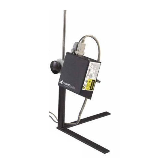
- Page 1 Quick Check® SV Series Bar Code Scanner/Verifier ™ User’s Guide...
- Page 2 Disclaimer Hand Held Products, Inc. (“Hand Held Products”) reserves the right to make changes in specifications and other information contained in this document without prior notice, and the reader should in all cases consult Hand Held Products to determine whether any such changes have been made. The information in this publication does not represent a commitment on the part of Hand Held Products.
-
Page 3: Statement Of Agency Compliance
Statement of Agency Compliance This device complies with part 15 of the FCC Rules. Operation is subject to the following two conditions: (1) this device may not cause harmful interference, and (2) this device must accept any interference received, including interference that may cause undesired operation. -
Page 4: Laser Beam
The SV Series should be used only with printers, applicators, conveyors, etc. that are UL listed. The SV Series is intended to be supplied by a UL Listed power supply (QCOLVPS) or receives power from the host unit (UL Listed Printer), output rated 5Vdc, minimum 300mA maximum 2A. -
Page 5: Laser Safety
Laser Safety • SV100C; IEC Class 3, CDRH Class III • All other SV models; IEC Class 2, CDRH Class II Enclosure Description... -
Page 7: Table Of Contents
Table of Contents Chapter 1 - Quick Check SV Series Introduction... 1-1 SV Series Model Specifications ... 1-2 ScanView Software ... 1-2 Laser Beam ... 1-2 Chapter 2 - Control Panel Reset Button... 2-1 Turn Off Laser Beam ... 2-1 Perform Calibration... - Page 8 Ladder Direction ... 5-8 Setting Ladder Mode Scanning Length Using ScanView Software ... 5-8 Calibration ... 5-8 Adjusting Scanner Gain and Offset ... 5-10 Chapter 6 - SV Command Language Introduction... 6-1 Data Match Commands – B... 6-1 Relationship Between ~BC and ~Br Commands ... 6-5 Diagnostic Commands –...
- Page 9 Mode 18 (~LV18)... 6-45 Mode 19 (~LV19)... 6-49 Mode 20 (~LV20)... 6-52 Chapter 7 - ISO Parameter Grade Thresholds Chapter 8 - Technical Specifications Scanning Performance–SV Series Model ... 8-2 Scanner Options ... 8-2 Power... 8-2 Sync ... 8-2 Outputs ... 8-3 Symbologies ...
- Page 10 For Further Information ... 9-2 Product Service and Repair ... 9-2 Online Product Service and Repair Assistance... 9-3 Limited Warranty... 9-3 Chapter A - SV Series Setup Hints - Scanning Distance and Angle Introduction...A-1 Setting the Proper Scan Distance...A-1 Setting the Proper Scan Angle...A-2...
-
Page 11: Chapter 1 - Quick Check Sv Series
The SV Series is available in different models. All models operate identically, but the scanner parameters, such as scans per second and focus distance, are different. -
Page 12: Sv Series Model Specifications
This program is available from Hand Held Products and authorized Hand Held Products re-sellers. ScanView can be used to program the SV Series via serial communication using SV download language. The language is described in this user’s guide. -
Page 13: Chapter 2 - Control Panel
Isolated synchronization input (-) Switch synchronization input Output Port 1 Output Port 2 Output Port 3 Output Port 4 Quick Check® SV Series User’s Guide (page "Calibration" on "Output Ports" on page 2-5 6-24) in for details. 2 - 1... -
Page 14: Vdc Power Input
(See page 6-1.) A sync signal is used to synchronize the SV Series to an object, label, etc. that contains the bar code(s) being analyzed as it passes through the laser beam. The SV Series should be programmed for the number of bar codes expected per sync interval. - Page 15 Signal input polarity is also user programmable. Please see "SV Command Language" on page 6-1 use of these sync modes. Quick Check® SV Series User’s Guide + 5 VDC (SV PSU TTL Sync Input Diagram 1N914 Isolated Sync Input Diagram...
-
Page 16: Edge Sync Mode
2. A serial communication report is transmitted, and an output port is updated per its programmed function each time a bar code is analyzed. 2 - 4 Sync sensed here Quick Check® SV Series User’s Guide... -
Page 17: Communication Sync Commands
The diagram below shows an example circuit diagram of one output port. From SV output logic Quick Check® SV Series User’s Guide for details. Open Drain FET Output Diagram "Output Interface Modes... -
Page 18: System Displays
Five LEDs are included on the SV Series back panel. Power/Sync LED This LED is illuminated green whenever power is applied to the SV Series. Upon receipt of any sync input (hardware or serial communications), the LED blinks yellow for approximately 100 milliseconds. -
Page 19: Chapter 3 - Serial Port Connector
Serial Port Pin-out Serial Port Transmission Format The following data transmission format is standard in the SV Series. This is the format used by ScanView software for setup and monitoring of SV Series data. All parameters analyzed for each bar code scanned are transmitted in the... - Page 20 + or - indicating sign of avg. min. bar deviation calculation. + indicates wide bars. Minimum bar deviation calculation averaged over all decoded scans. Units are in % of X. Value: 00-9A (signify 0 –100) Quick Check® SV Series User’s Guide (page 6-28) command.
- Page 21 Quick Check® SV Series User’s Guide Chars Parameters + or - indicating sign of avg. max. bar deviation calculation. + indicates wide bars. Maximum bar deviation calculation averaged over all decoded scans. Units are in % of X. Value: 00-9A (signify 0 – 100) One character: Pass(P) or Fail(F).
- Page 22 Programmable ASCII character indicates end of transmit; See 28) command. LF (line feed) required for ScanView. (page 6-18) for other transmission data formats. Symbology Category I 2 of 5 Code 128 Code 93 Quick Check® SV Series User’s Guide ~SSbbbeee (page 6-...
- Page 23 Identifiers Quick Check® SV Series User’s Guide Symbology Category Code 3 of 9 Codabar UPC-A UPC-A w/add-on (2) UPC-A w/add-on (5) EAN-13 EAN-13 w/add-on (2) EAN-13 w/add-on (5) EAN-8 EAN-8 w/add-on (2) EAN-8 w/add-on (5) UPC-E UPC-E w/add-on (2) UPC-E w/add-on (5)
- Page 24 3 - 6 Quick Check® SV Series User’s Guide...
-
Page 25: Chapter 4 - Scanview Installation And Setup
Introduction ScanView is designed to be a tool used for system setup and real-time bar code monitoring of a Hand Held Products SV type scanner/verifier. It is a Windows 2000/XP application with facilities for sending commands to the SV scanner/ verifier and receiving the responses. -
Page 26: Pc Communication Port Setup
ScanView will detect the verifier’s baud rate, and set the port to the detected value. 4 - 2 page 4-9 and described in the Analysis Screens 4-9). Then click the ‘Match Verifier Baud rate” menu Quick Check® SV Series User’s Guide "Bar Code... -
Page 27: Software Operation Warnings
Select Graphs This item allows the user to select which bar code analysis parameter graphs are displayed on the Bar Code Analysis Screen (see "Bar Code Analysis Screen" on page 4-9.) Quick Check® SV Series User’s Guide 4 - 3... - Page 28 This item allows the user to program the SV scanner/verifier baud rate. Match Verifier Baud Rate This item detects the baud rate of an SV scanner/verifier; then it changes the ScanView baud rate setting to the detected value. This is useful when using ScanView as a diagnostic tool in a system that is using the SV communication interface.
-
Page 29: Advanced Menu
Hand Held Products’ Technical Support. Download New Firmware This item is used for updating the firmware revision level in an SV scanner/ verifier. Port Configuration This item lets the user configure the SV unit output port activation threshold settings. -
Page 30: Speed Button Bar - Screen Display
Screen" on page 4-12.) The shortcut key for this function is F3. 4 - 6 4-9. The buttons on this bar give quick 4-9) is updated immediately as the SV scanner/verifier Quick Check® SV Series User’s Guide "Bar Code "Reflectance Profile... -
Page 31: Modes Of Operation
(selected by the user). The Windows communications facility has a data buffer that allows the graph processing to ‘catch up’ between bursts of transmitted data. If the incoming data volume Quick Check® SV Series User’s Guide 4 - 7... -
Page 32: Analysis Screens
An example is shown below. Each individual parameter analysis result for one bar code is indicated by a dot on a parameter graph in the Graph Display Area and can be easily accessed via the mouse. 4 - 8 Quick Check® SV Series User’s Guide... - Page 33 Display Area). Results for other bar codes may be reviewed by dragging the mouse pointer (while holding down the left mouse button) to the data point of interest in the Graph Display Area. Quick Check® SV Series User’s Guide Bar Code Analysis Results...
- Page 34 Setup Menu in the Menu Bar. Click on the Select Graphs menu item. 4 - 10 above exhibits the analysis results for (page 4-6)), if enough bar codes are "Bar Code Analysis Screen" on Quick Check® SV Series User’s Guide...
-
Page 35: Color Coding
Dot indicates the ISO grade value of a bar code. Reflectance Profile Screen This screen displays a reflectance profile for SV unit’s entire scan path. An example is shown below. Quick Check® SV Series User’s Guide Color/Grade Reference Chart Color/Grade Bar 4 - 11... - Page 36 This high reflectance spans includes one of the bar code quiet zones. The amplitude of the bar code signal is in the desired location between the yellow lines (10% and 90% of dynamic range) path. Quick Check® SV Series User’s Guide...
-
Page 37: Chapter 5 - Scanner Setup
Scanner Setup Scanner positioning and proper system setup are extremely important for proper SV Series operation. The following sections describe the most common setup possibilities in detail. Some knowledge of SV Series operation is recommended to best follow the steps. Please refer to Appendix A... -
Page 38: Scanner Positioning
Scanner Positioning Each SV Series has an attached label that indicates the type of scanner, focus distance and recommended scan angle. Use the scan distance and scan angle information in the following illustration to mount the scanner. Laser Beam Scan Angle... -
Page 39: Bar Code Travel Direction
A bar code should be present in the beam for at least five scans for the most reliable operation. The SV Series performs a minimum of 100 scans/analyses per second. At that rate, each analysis is accomplished in 10 milliseconds maximum. - Page 40 Adjust distance of the SV100 from the bar code until the X dimen- sion matches the desired value. (If X is analyzed as too large, move the scanner farther away; if X is too small, move the scanner closer.) 7. Repeat steps 8.
- Page 41 Each SV unit is supplied with a calibration symbol. 11. The SV scanner/verifier is now ready to operate for picket fence bar code travel direction. If Ladder Mode is being used and the desired scanning length for ladder bar code travel direction is programmed, place the unit in ladder mode.
- Page 42 In this orientation, the beam is sweeping from left to right. Refer to Setup" on page 5-1. Good Reflectance Profile 5 - 6 Example of “good” scan reflectance profile: • Consistent amplitude • Amplitude within yellow lines Quick Check® SV Series User’s Guide "Scanner...
-
Page 43: Bad Reflectance Profile
Vertical distance between bar codes is also a speed consideration in picket fence direction. The SV Series must have five continuous scans where no bar code is detected to reliably exit a bar code when operating in the standard operation mode set by Command ~HO1. -
Page 44: Picket Fence Bar Code Positioning Specifications
A calibration symbol is supplied with each SV unit as a standard component. Store this symbol in a clean location. The SV Series can be calibrated using either of the two following procedures: 5 - 8 Quick Check® SV Series User’s Guide... - Page 45 – either on its mounting stand or into a new location. It is advised to keep the laser beam exit window clean. Dirt, dust, and fingerprints on the exit window can affect calibration. Quick Check® SV Series User’s Guide 5 - 9...
-
Page 46: Adjusting Scanner Gain And Offset
Adjusting Scanner Gain and Offset Scanner gain and offset adjustment via commands is available in SV units that have the “A” circled on the label that indicates focus distance. The adjustment capability is useful for adapting the unit to various material types and scanning angles during the setup procedure. - Page 47 Desired Signal Amplitude and Placement Quick Check® SV Series User’s Guide • Bar code signal amplitude at least 6 lines high. (A more preferred 7 lines high is shown in this example.) • Bar code signal placement within the 5 - 11...
- Page 48 5 - 12 Quick Check® SV Series User’s Guide...
-
Page 49: Chapter 6 - Sv Command Language
An important consideration when using data match type commands is the data format. These commands incorporate a “scanner” philosophy rather than a “verifier” philosophy. A scanner philosophy is to report the data encoded in a symbol while a verifier philosophy is to report all symbol characters whether they include data or not. - Page 50 Data Match Character Field. This can be from 1 to 32 char- acters. These define the exact characters that must be matched..bbb... Fill characters after to the Data Match text (if needed) 6 - 2 Quick Check® SV Series User’s Guide...
- Page 51 0-9 only. If set to 1, the check is per- formed for alphanumeric characters 0-9, A-Z. Quick Check® SV Series User’s Guide Data match array #0 with 5 characters of “ABCDE” of fixed length with ‘x’ as the ignore or fill character.
- Page 52 C34 (base 36 alphanumeric field). Decrement is to be done in location 6 through 8 characters of the 10 character array. Disable the Increment/Decrement array. The remainder of the array data is not required. Quick Check® SV Series User’s Guide...
-
Page 53: Relationship Between ~Bc And ~Br Commands
(a ‘counts’ value), then a ‘\r’ character (carriage return) and a ‘\n’ character (a line feed). 4. hexadecimal value ‘5’ - identifies the end of the data packet response 5. F - the last character of the sent command string Quick Check® SV Series User’s Guide 6 - 5... -
Page 54: Hardware Configuration Commands - H
# = 1 through 8 (port ID) Inquire firmware version. 1. Commands the verifier to transmit the SV Series firmware version to the host in the following data packet format: 2. ~D 3. hexadecimal value ‘4’ - identifies the beginning of the data packet response 4. - Page 55 Select “Ladder” or “Picket Fence” bar code travel direction mode. Values for # are: Ladder Picket Fence ~HO# Operational Mode Values for # are: (inhibit output) Use this state only when downloading Quick Check® SV Series User’s Guide 6 - 7...
- Page 56 Example: (The numbers of parameters reported varies with the com- mands included in the firmware revision) {hex 4} [~HS###]SOS= 048 [~HP###]Beam Shift= 000 000 [c]HIGHcal= 085 [c]LOWcal= 002 [~Sh##]= 000 6 - 8 ~De# (page 6-6) command for Quick Check® SV Series User’s Guide...
- Page 57 [~LD##] %dec= 000 [~PR####]PRST= 000200 [~HL#]ladder_code= 000 [~HJ####]ladd_start= 0800 [~HK####]ladd_end= 1600 [~HC####]ana_len= 2600 [~HG####]ana_lenh= 1300 [~HN####]pana_len= 1300 [~HU####]freq= 400 [~HV###]GTLA_len= 199 [~HY###]snoise= 070 [~HX###]dist= 078 [~H=#]dyn_out= 000 [~H!###]zone_tol= 450 [~H@##]gt_%= 050 Quick Check® SV Series User’s Guide 6 - 9...
- Page 58 ~Hdx01nnn Sets scanner gain or offset. x = value of 1 or 2. If =1, scanner gain is set. If = 2, scanner offset is set. nnn = gain or offset setting. For gain, the higher the value, the higher the gain. 225 is the max allowed value.
-
Page 59: Label Setup Commands - L
= failure threshold. Example ~LD75: if 74 % or less of scans on a code were not fully decoded, this sets a failure for this parameter. Quick Check® SV Series User’s Guide 6 - 11... - Page 60 Example: ~LF41 = check mod 10 check digit in last location for any I 2 of 5 symbol analyzed ~LF40 = disable any subsymbology analysis for I 2 of 5 symbols 6 - 12 Quick Check® SV Series User’s Guide...
- Page 61 Hexadecimal value ‘5’ - identifies the end of the data packet response L - the last character of the sent command string Example return using ScanView: UPC/EAN- IN C39- IN C128- IN CITF- IN C93- IN CBAR- IN min chars: number bc: Quick Check® SV Series User’s Guide 6 - 13...
- Page 62 SV unit. ~LP# Set Sync Polarity (See "Sync Inputs" on page 2-2 ities.) Falling edge of signal is active Rising edge of signal is active 6 - 14 for examples of sync input polar- Quick Check® SV Series User’s Guide...
- Page 63 ~SSbbbeee command. Therefore it may not be compatible with setup with ScanView. A No Read transmission is not available with this setting. Quick Check® SV Series User’s Guide "Serial Port Transmission Format" on page 3-1 6 - 15...
- Page 64 ~LT# Sync Input Source Isolated Input (Pins 1(+), 2(-)) TTL Input (Pin 4) Communication Sync 6 - 16 (page 6-24) command for ##=01; single scan mode) Quick Check® SV Series User’s Guide...
- Page 65 Some activation parameters are programmable. Custom modes are available – contact Hand Held Products Technical Support. Modes included in standard SV Series are described in the "Output Interface Modes Descriptions" on page mode 01.
-
Page 66: Output Mode Selection Commands - O
The data consists only of printable ASCII characters and does not include any mandatory symbol characters such as stop, start and symbol mod check characters. One exception is in UPC/EAN codes, the mod 10 check digit is included. 6 - 18 Quick Check® SV Series User’s Guide... -
Page 67: Output Port Setup Commands - P
Table of Analysis Parameters Analysis Parameters Overall Grade Decodabil- Modulation Quick Check® SV Series User’s Guide for details of port logic. The ~PB and for details on the values of High Units Grade "Output Interface for ID descriptions) for ~PB command... - Page 68 Min Chars Percent Decode 6 - 20 High Units Mils -100 % of X -100 % of X -100 % of X Ratio X-dim Flag Scans Quick Check® SV Series User’s Guide High Value Value 000* 200* 000* 200* 000* 200*...
- Page 69 Value of action- aaa Table of Action Parameters Description Pulse width (0.1s to 10.0s; > 10.0= latch) Active State high or Set port on Good/ Bad Evaluation Quick Check® SV Series User’s Guide High Units Flag Flag Flag Flag Flag...
- Page 70 005 - 255 255 006 - 021 000 007 - 255 255 008 - 255 255 009 - 255 255 010 - 255 255 011 - 010 050 012 - 255 255 6 - 22 Quick Check® SV Series User’s Guide...
- Page 71 Each port and led are represented by a binary digit in the four hexadecimal digits as follows: Indicator Power Indicator Read LED LED1 LED2 Port 1 Port 2 Port 3 Port 4 Port 5 Quick Check® SV Series User’s Guide Digit Value 0x0001 0x0002 0x0004 0x0008 0x0010 0x0020 0x0040 0x0080 0x0100 6 - 23...
-
Page 72: System Control Commands - S
When n=1, a single scan of can be used to capture and analyze a bar code, enabling bar codes to be analyzed while traveling through the laser beam at high speeds. 6 - 24 Digit Value 0x0200 Quick Check® SV Series User’s Guide... -
Page 73: How To Set Up Single Scan Operation
The normal way of checking system status is with the ~HT command. The newer commands ~SB and ~Hn are not displayed with the standard ~HT command. In order to display the additional commands, set command ~De1 to allow the alternate ~HT reply. Quick Check® SV Series User’s Guide 6 - 25... - Page 74 Set Scanner Gain and Offset for symbol that is in the laser beam This command automatically sets the scanner gain and offset to a bar code that is in the laser beam. Place the SV unit in moving codes mode to use this command.
- Page 75 This command shows beams for all eight polygon facets for 4 seconds, then shows a beam for one facet for 4 seconds. Ideally, the beam widths will look identical in non-raster type scanners. Acceptable difference in most cases is 1/ inch. Quick Check® SV Series User’s Guide 6 - 27...
- Page 76 ~SS has a fixed single character for both start and end of the transmission. x = number of characters in the header. Allowed values are 0,1,…9 therefore up to nine header characters are available. 6 - 28 Quick Check® SV Series User’s Guide...
- Page 77 010 = decimal value of ASCII character LF which will be second (and final) trailer character sent ~Ssxy Command Example 2; ~Ss11080086 One header character P will be sent and one trailer character V will be sent Quick Check® SV Series User’s Guide 6 - 29...
-
Page 78: Output Interface Modes Descriptions
Valid command syntax is [LV00 instead of the default ~LV00 Output Interface Modes Descriptions Output interface modes are used to set the SV Series for particular ways to activate output ports. The mode is set via the ~LV## command. The following list describes the standard output interface modes available in SV firmware versions x270 and higher. -
Page 79: Mode 01 (~Lv01)
1. LED1 will turn on if Outputs 1 and 2 go active due to ISO, contrast, or quiet zone failure 2. LED2 will turn on if Outputs 1 and 2 go active due to a partial or no read condition Quick Check® SV Series User’s Guide 6 - 31... - Page 80 The field xxx is the passing threshold for the calculation. For example: if xxx = 025, a Defects analysis of 26% or higher will cause a failure condition for this parameter. 6 - 32 Quick Check® SV Series User’s Guide...
-
Page 81: Mode 02 (~Lv02)
The port shall go active (sink current) for the following conditions; a. ISO Defects grade programmable (~PB806xxx000) b. ISO Decodability grade programmable (~PB802xxx100) Quick Check® SV Series User’s Guide 6 - 33... - Page 82 This command turns off all partial decode logic at the decoder level ~Lp1 This command turns on partial decode logic at the decoder level ~LQ1 This command allows partial decodes to activate the output ports 6 - 34 Quick Check® SV Series User’s Guide...
- Page 83 This command sets the exact number of codes to be read during a sync period. ## = the number of codes. For example: ~LZ02 causes a No Read condition to be set if exactly 2 bar codes are not fully decoded during a sync interval. Quick Check® SV Series User’s Guide 6 - 35...
-
Page 84: Mode 03 (~Lv03)
8. Pushing the reset button or power re-cycle will place Ports 1- 4 in their inactive states. 9. Error conditions available are: a. Partial Read (~Lp#, ~LQ#) b. % decode programmable, ( ~LD##) c. Bad Quiet Zone (~PB816xxx100) 6 - 36 Quick Check® SV Series User’s Guide... - Page 85 This command turns on partial decode logic at the decoder level ~LQ1 This command allows partial decodes to activate the output ports ~LQ0 This command disables partial decodes to activate output ports. Quick Check® SV Series User’s Guide 6 - 37...
- Page 86 2 bar codes are not fully decoded during a sync interval. This command overrides the ~LN## command if the number of codes set does not = 00. If ~LZ## is set to ~LZ00, the ~LN## command takes precedence. 6 - 38 Quick Check® SV Series User’s Guide...
-
Page 87: Mode 16 (~Lv16)
ISO Decodability grade less than C (Programmable, ~PB802xxx100) Symbol Contrast grade less than D (Programmable, ~PB804xxx100) g. Overall ISO Grade (Programmable, ~LAxx) h. No Read (if sync is received) Number of codes per sync programmable (~LN##, ~LZ##) Quick Check® SV Series User’s Guide 6 - 39... - Page 88 = failure threshold. Example ~LD75: if 74 % or less of scans on a code were not fully decoded, this sets a failure for this parameter. 6 - 40 Quick Check® SV Series User’s Guide...
- Page 89 2 bar codes are not fully decoded during a sync interval. This command overrides the ~LN## command if the number of codes set does not = 00. If ~LZ## is set to ~LZ00, the ~LN## command takes precedence. Quick Check® SV Series User’s Guide 6 - 41...
-
Page 90: Mode 17 (~Lv17)
Overall ISO Grade (Programmable, ~LAxx) h. No Read (if sync is received) Number of codes per sync programmable (~LN##, ~LZ##) X dimension Range (Programmable ~PB811xxxyyy) k. Ratio (Programmable ~PB815xxx000) Symbology Mod Check data error 6 - 42 Quick Check® SV Series User’s Guide... - Page 91 This command sets the passing threshold for the Overall ISO method Symbol Grade. For example: ~LA28 causes an Overall Symbol Grade of 2.7 or lower calculated for the code analyzed to set a failure condition for this parameter. Quick Check® SV Series User’s Guide (~BC). 6 - 43...
- Page 92 X dimension. The value yyy is the widest acceptable X dimension. Units are in .001 inch (mils). For example: ~PB811010020 will cause a failure for an X dimension less than 10 mils or greater than 20 mils. 6 - 44 Quick Check® SV Series User’s Guide...
-
Page 93: Mode 18 (~Lv18)
9. Port 5 pulse time programmable (~PP801xxx). Pulses will act like a re- triggerable 1-shot. 10. Pushing the reset button or power re-cycle will place Ports 1- 5 in their inactive states. Quick Check® SV Series User’s Guide (page 6-17) command below for priority. 6 - 45... - Page 94 5. Flashing indication will override a solid on indication if both types of error conditions occur. Note: Both LEDs can be on in cases where multiple bar codes are analyzed in a sync period. 6 - 46 Quick Check® SV Series User’s Guide...
- Page 95 Example: if xxx = 030, a minimum of 30% of all fully decoded scans on a code must calculate a good quiet zone, or a failure condition is set for this parameter. Quick Check® SV Series User’s Guide 6 - 47...
- Page 96 2 bar codes are not fully decoded during a sync interval. This command overrides the ~LN## command if the number of codes set does not = 00. If ~LZ## is set to ~LZ00, the ~LN## command takes precedence. 6 - 48 Quick Check® SV Series User’s Guide...
-
Page 97: Mode 19 (~Lv19)
4. Port 1; acts as strobe (signal ensuring Port 3 condition is stable) in response to trailing edge of sync input. This signal will go “on” (sink current) between 20 and 100 microseconds after Port 3 condition is stable. Quick Check® SV Series User’s Guide 6 - 49... - Page 98 This command sets the passing threshold for the Overall ISO method Symbol Grade. For example: ~LA28 causes an Overall Symbol Grade of 2.7 or lower calculated for the code analyzed to set a failure condition for this parameter. 6 - 50 Quick Check® SV Series User’s Guide...
- Page 99 ## = the number of codes. For example: ~LN02 causes a No Read condition to be set if less than 2 bar codes are fully decoded during a sync interval. See the ~LZ## (page 6-17) command below for priority. Quick Check® SV Series User’s Guide 6 - 51...
-
Page 100: Mode 20 (~Lv20)
Mode 20 (~LV20) This mode is identical to Mode 19 with the exception the sync polarity is reversed. The leading edge is low going. 6 - 52 Quick Check® SV Series User’s Guide... - Page 101 ISO Parameter Grade Thresholds ISO parameter fail thresholds are set in the SV Series by commands requiring numeric settings that correlate to the parameter calculations. Following are descriptions of how the numeric calculations are divided into letter grades per the ISO Bar Code Quality Specification.
- Page 102 Reference Decode A = ISO method algorithm decoded the symbol F = ISO method algorithm could not decode the symbol 7 - 2 Quick Check® SV Series User’s Guide...
-
Page 103: Chapter 8 - Technical Specifications
Wavelength Beam Shape Class II Laser Product (SV100C is Class IIIa) Quick Check® SV Series User’s Guide Specification 4.4” (112 mm) x 2.4” (61mm) x 5.2” (132 mm) 5 LEDs - PowerSync, Calibration, Read, 2 Programmable LEDs 1 and 2... -
Page 104: Scanning Performance-Sv Series Model
10.5” (114mm) (267mm) 6” 15” (152mm) (381mm) .005” .013” (.127mm) (.33mm) Technical Assistance Technical Assistance (see page for more details Quick Check® SV Series User’s Guide SV200-1 SV200-2 2.5” 1.75” (63.5mm) (44mm) 8” 6” (203mm) (152mm) .0067” .005” (.17mm) (.127mm) (see page 9-1) 9-1). -
Page 105: Outputs
• EAN-13 and EAN-8 (including 2 and 5 digit supplemental codes) Operation Modes The SV Series is very flexible, with many programmable features, but basic system operation can be broken down into three modes. Two modes include a sync signal and one mode operates without a sync signal. These modes are programmable via SV Command Language Products’... -
Page 106: Sync Mode - Stationary Bar Codes
It is recommended to use serial communications to a host in this mode for the host to determine missing codes. If this mode is used, the SV Series can still detect many print errors because of its partial decode analysis capability. This algorithm can detect a bar code start or stop character and two adjacent characters. - Page 107 • Symbology Type (scanner decoder function) • % Decode (multiple scanning parameter) • Global Threshold (ISO method parameter) • Modulo Check Digits (mandatory symbology and optional application parameters) • Encoded Data (scanner decoder function) Quick Check® SV Series User’s Guide 8 - 5...
- Page 108 8 - 6 Quick Check® SV Series User’s Guide...
-
Page 109: Chapter 9 - Maintenance/Customer Support
Maintenance/Customer Support Maintenance The Quick Check SV Series is designed to provide maintenance-free operation through its life and contains no moving parts that require maintenance. Repairs and/or upgrades are not to be performed on this product. These services are to be performed only by an authorized service center. -
Page 110: Online Technical Assistance
Telephone: (803) 835-8000 Telephone: (800) 782-4263 Fax: (239) 263-9689 E-mail: laservice@handheld.com Brazil Telephone: +55 (21) 2178-0500 Fax: +55 (21) 2178-0505 E-mail: brservice@handheld.com Mexico Telephone: +52 (55) 5203-2100 Fax: +52 (55) 5531-3672 E-mail: mxservice@handheld.com 9 - 2 Quick Check® SV Series User’s Guide... -
Page 111: Online Product Service And Repair Assistance
Held Products determines to its satisfaction that the product is defective due to defects in materials or workmanship, Hand Held Products, at its sole option, will either repair or replace the product without charge, except for return shipping to Hand Held Products. Quick Check® SV Series User’s Guide 9 - 3... - Page 112 Hand Held Products, Inc. extends these warranties only to the first end- users of the products. These warranties are nontransferable. The limited duration of the warranty for the Quick Check SV Series is for 1 year. 9 - 4...
-
Page 113: Chapter A - Sv Series Setup Hints - Scanning Distance And Angle
The specified scan distance is indicated on a label on the side of each unit. The SV Series' feature of being able to measure a bar code's X dimension makes it convenient for setting up scan distance. In the manufacturing process each SV unit is programmed to accurately measure the X dimension when scanning at the optimum distance. -
Page 114: Setting The Proper Scan Angle
2) is set, the SV unit does not have to be moved again. Session Mode Screen Showing the X Dimension Measurement Setting the Proper Scan Angle The SV Series requires a fixed scanning angle for two basic reasons: 1. To maintain proper scanner signal levels in order to effectively decode symbols. - Page 115 SV units incorporate proprietary, analog scanners. The scanner gain and offset are adjustable, allowing the units to adapt to practically any material. ScanView software allows easy setup of scanner gain and offset. A quick method of adjusting the scanner using a special command ~Sc is described below. If the "quick method"...
- Page 116 See "Calibration Hints" on page Note: At this point the scanner is set up for the material in the application and the ~Sc command has been used at least once to change the scanner's setting from the initial state.
-
Page 117: Calibration Hints
% reflectance. Calibration affects reflectance calculations only. Calibration does not affect any other calculations or ability to decode a symbol, etc. The scanner gain and offset settings have the major effect on scanning performance. Keeping the scanner signal linear (between the yellow lines as described previously) is very helpful for good decoding, but is CRUCIAL for reflectance measurements. - Page 118 A - 6 Quick Check® SV Series User’s Guide...
- Page 120 Hand Held Products, Inc. 700 Visions Drive P.O. Box 208 Skaneateles Falls, NY 13153-0208 QCOLVSV-UG Rev C 10/07...