Advertisement
Table of Contents
Advertisement
Table of Contents

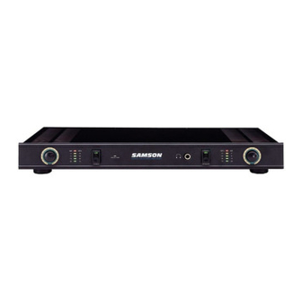
Summary of Contents for Samson Servo 120
- Page 1 S E R V O 1 2 0 AMPLIFIER OWNERS MANUAL ®...
-
Page 2: Table Of Contents
Servo 120 Features 4 Guided Tour 5 Front Panel 5 Rear Panel 6 Setting Up and Using the Servo 120 Amplifier 7 The Servo 120 Protection Circuitry 8 Bridge Mode 9 Appendix A: Linearity vs. Frequency Sweep 10 Appendix B: Power Output vs. THD 11... -
Page 3: Introduction
Servo 120 the perfect complement to any recording studio. • Home Theatre applications - The power and flexibility offered by the Servo 120 (it can be used either as a 60 watt stereo amplifier, or, in bridge mode, as a 120 watt monophonic amp) makes it the perfect addition to any home theatre, in conjunction with any DVD player or other surround sound system. -
Page 4: Servo 120 Features
• Protection relay circuitry (linked to the DC offset circuitry) that prevents “thumps” when powering on or off. This means that you can use the Servo 120 with a single power strip into which a mixer or other audio devices are connected, without danger of damage to connected speakers. -
Page 5: Guided Tour
-16 dB / 15%, -10 dB / 30%, -6 dB / 50%, -3 dB / 70%, and 0 dB / 100%. When the bottom (-16 dB / 15%) segment is lit, the Servo 120 is operating at approximately 15% of its power capacity. -
Page 6: Rear Panel
Stereo signals should be connected to both the left and right input jacks; when operating the Servo 120 in Bridge mode, use the left input jack only (see page 7 in this manual for more information). The Servo 120 accepts input levels of any strength but needs at least +4 dBu to achieve maximum power. -
Page 7: Setting Up And Using The Servo 120 Amplifier
(you’ll hear a click when this occurs). Protection LED 7. Apply an input signal to the Servo 120 at or about +4 dBu (if sending signal from a mixer, drive the output meters at approximately 0 vu). While the input signal is present, slowly raise the Channel Input controls until the desired sound level is achieved. -
Page 8: The Servo 120 Protection Circuitry
The Servo 120 Protection Circuitry As noted in the “Guided Tour” section of this manual, the Servo 120's front panel Protection LED indicates the activity of the relay speaker connection circuitry. When the Protection LED is lit, this circuitry is inactive, and all connected... -
Page 9: Bridge Mode
Bridge Mode The Servo 120 provides a rear-panel switch that allows it to be used in a Bridge mode. When this switch is placed in the “Off” (left) position, the Servo 120 BRIDGE functions as a true stereo amplifier, where both of the two independent amplifier channels (left and right) can receive different input signals and produce independent output signals. -
Page 10: Appendix A: Linearity Vs. Frequency Sweep
Appendix A: Linearity vs. Frequency Sweep AUDIO PRECISION Servo 120 LEVEL (dBr) vs FREQ (Hz) 0dB ref 5.0000 4.0000 3.0000 2.0000 1.0000 -1.000 -2.000 -3.000 -4.000 -5.000 Linearity (0 dB Ref) vs. frequency sweep 10 Hz - 50 kHz... -
Page 11: Appendix B: Power Output Vs. Thd
Appendix B: Power Output vs. THD AUDIO PRECISION Servo 120 THD +N (%) & LEVEL (W) vs FREQ (Hz) Watts 80.000 1.000 73.000 .9000 61.000 .8000 56.000 .7000 48.000 .6000 40.000 .5000 32.000 .4000 21.000 .3000 15.000 .2000 8.000 .1000 200.0u... -
Page 12: Specifications
Specifications 1. Rated Output Power, per channel (@ 1 kHz) Stereo mode 4 ohm, .<0.05% THD+N 60 W 4 ohm, 1% THD+N 80 W 8 ohm, <0.05% THD+N 50 W 8 ohm, 1% THD+N 55 W Bridge mode 8 ohm, .<0.05% THD+N 120 W 8 ohm, 1% THD+N 150 W... - Page 13 Produced by On The Right Wavelength for Samson Technologies Corp. Copyright 1997, Samson Technologies Corp. Printed June, 1997 Samson Technologies Corp. 575 Underhill Blvd. P.O. Box 9031 Syosset, NY 11791-9031 Phone: 1-800-3-SAMSON (1-800-372-6766) Fax: 516-364-3888...


Need help?
Do you have a question about the Servo 120 and is the answer not in the manual?
Questions and answers