Table of Contents
Advertisement
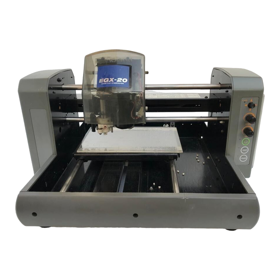
DESKTOP ENGRAVER
EGX-20
USER'S MANUAL
Thank you very much for purchasing the EGX-20.
•
To ensure correct and safe usage with a full
understanding of this product's performance,
please be sure to read through this manual
completely and store it in a safe location.
•
Unauthorized copying or transferral, in whole or in
part, of this manual is prohibited.
•
The contents of this operation manual and the
specifications of this product are subject to change
without notice.
•
The operation manual and the product have been
prepared and tested as much as possible. If you
find any misprint or error, please inform us.
•
Roland DG Corp. assumes no responsibility for
any direct or indirect loss or damage which may
occur through use of this product, regardless of
any failure to perform on the part of this product.
Advertisement
Table of Contents

Subscribe to Our Youtube Channel
Related Manuals for Roland EGX-20


Summary of Contents for Roland EGX-20
- Page 1 DESKTOP ENGRAVER EGX-20 USER'S MANUAL Thank you very much for purchasing the EGX-20. • To ensure correct and safe usage with a full understanding of this product's performance, please be sure to read through this manual completely and store it in a safe location.
- Page 2 AVIS Cet appareil numérique de la classe A respecte toutes les exigences du Règlement sur le matériel brouilleur du Canada. ROLAND DG CORPORATION 1-6-4 Shinmiyakoda, Hamamatsu-shi, Shizuoka-ken, JAPAN 431-2103 MODEL NAME : See the MODEL given on the rating plate.
-
Page 3: How To Use This Manual
In Windows, click [Start]. From the menu, point to [Programs], then [Roland 3D Engrave], then select [3D Engrave Help]. The help window appears. In the same way, point to [Roland Dr. Engrave] and select [Dr. Engrave Help], or point to [Roland Virtual MODELA] and select [Virtual MODELA Help]. -
Page 4: Table Of Contents
Performing Cutting ..............................38 5. Important Notes, Limitations, and Other Information........39 Important Notes and Limitations ........................... 39 Functions Using the Switch Panel on the EGX-20 ....................40 6. Other Information ....................41 Replacement Cutters ............................. 41 Daily Care and Maintenance ..........................41 What to Do If... -
Page 5: To Ensure Safe Us
Use with other than the included power cord may lead to fire or electrocution. Doing so may result in fire or electrical shock. Immediately unplug the power-cord plug from the electrical outlet, and contact your authorized Roland DG Corp. dealer or service center. - Page 6 Do not use with a damaged AC Do not injure or modify the electrical adapter, power cord, or power-cord power cord, nor subject it to plug or with a loose electrical outlet. excessive bends, twists, pulls, Use with any other binding, or pinching, nor place any power supply may object of weight on it.
-
Page 7: About The Labels Affixed To The Ac Adapter And Uni
About the Labels Affixed to the AC Adapter and Unit These labels are affixed to the body of this product and the AC adapter. The following figure describes the location. Handle tool with care. Model name Rating label Do not use with any electrical power supply that does not meet the ratings displayed on the AC adapter. -
Page 8: Getting Ready
EGX-20 USER'S MANUAL 1 Getting Ready What You Can Do with the EGX-20 • You can engrave a plate with text or shapes to create a nameplate or the like. Using Dr. Engrave, the included 2D engraving program, you can easily engrave anything from simple text to complex designs to produce high-quality engraved plates. -
Page 9: Names And Functions
1 Getting Ready Names and Functions The names of the parts of the EGX-20 are as follows. Front Cover Carriage Switch Panel Spindle unit Spindle motor Z-axis light Movement button Speed control Spindle Speed control Power light Power button View light... -
Page 10: Setting Up And Connection
• Places where the installation surface is unstable or not level. • Places with excessive electrical noise. • Places with excessive humidity or dust. • The EGX-20 generates heat when used, and should not be installed in an area with poor heat radiation characteristics. • Places with excessive vibration. -
Page 11: Connecting To The Computer
1 Getting Ready Connecting the AC Adapter and Power Cord Connect in the order of the numbers shown in the figure. AC adapter jack AC adapter Power cord Connecting to the Computer To connect the machine and the computer, you can use either a parallel cable (IEEE 1284-compliant) . The parallel cable is sold separately. -
Page 12: Attaching The Adhesive Sheet
EGX-20 USER'S MANUAL Attaching the Adhesive Sheet You use the included adhesive sheet to secure material to engrave to the table on the EGX-20. First you need to install the included adhesive sheet on the table. NOTICE Be sure the unit is in View status when attaching the adhesive sheet. -
Page 13: Installing The Blade Holder
1 Getting Ready Installing the Cutter Holder Before you install a cutter, you need to install the included cutter holder on the spindle unit. A cutter holder is attached to the included cutter. Remove the cutter from the cutter holder. Cutter Cutter holder Open the cover for the carriage. -
Page 14: Installing And Setting Up The Software
To use the EGX-20, you need to install the driver on the computer connected to the EGX-20. The EGX-20 also comes with a number of programs for creating engraving and cutting data, which you can use to match the target task. - Page 15 CD-ROM drive, then double-click "CDMenu.exe" to run it. Click the drop-down arrow for [Click here], then from the menu that appears, select [EGX-20]. If your computer is connected to the Internet, the Roland DG Corp. website appears. Check this for information about updates to the driver and the like.
- Page 16 EGX-20 USER'S MANUAL You can choose to install and set up a program by selecting its corresponding check box. If you do not want to install a particular program, than clear the corresponding check box. Normally you should select all check boxes.
- Page 17 When installation of 3D Engrave finishes, the [EGX-20 Driver Installation] dialog box appears. Choose the port for connecting the EGX-20. The EGX-20 connects to a printer port. If your computer has a single printer port, select [LPT1:]. Click [OK]. The EGX-20 driver is installed.
-
Page 18: Creating A Nameplate (Operations In The Engraving Mode)
EGX-20 USER'S MANUAL 3 Creating a Nameplate (Operations in the Engraving Mode) This section describes the basic steps for engraving using the EGX-20, taking the procedure for engraving the plate included with the machine as an example. Loading Material You use the included adhesive sheet to secure material to engrave to the table on the EGX-20. -
Page 19: Installing A Cutter
When movement ends, the View light goes dark. Origin Point The origin point is a reference point that the EGX-20 uses for starting engraving. When the machine is shipped from the factory, the origin point is set at the lower left corner of the table. - Page 20 EGX-20 USER'S MANUAL Insert the cutter into the hole in the cutter holder, then slowly lower the cutter. Lower until the cutter touches the plate. Before you install a cutter, install the cutter holder. NOTICE See --> p. 11 "Installing the Cutter Holder"...
-
Page 21: Setting The Origin Point
3 Creating a Nameplate (Operations in the Engraving Mode) Setting the Origin Point When loading material, be sure to set the origin point. The origin point is the reference point for engraving. You set it individually for each piece of material you load. Omitting this operation may result in locations other than the material being engraved. -
Page 22: Creating Data With Dr. Engrave
The following explanation is for Windows 95/98/Me. For an explanation for Windows NT 4.0/2000, or for a more detailed explanation, see the help for Dr. Engrave or refer to the Dr. Engrave User's Manual (PDF) on the Roland Software Package CD-ROM. Starting Dr. Engrave In Windows, click the [Start] button. - Page 23 3 Creating a Nameplate (Operations in the Engraving Mode) Entering Text Enter the text to engrave on the plate. At the toolbar, click Click the location in the engraving area where you want to type in text, then enter the text using the keyboard. Engraving area Selecting the Font Specify a font for the text string you entered.
- Page 24 EGX-20 USER'S MANUAL Working with Text Strings You can resize and deform a text string by manipulating the points displayed around the string. Resizing and Moving You can change the size by dragging. At the toolbar, click , then click the text string.
- Page 25 3 Creating a Nameplate (Operations in the Engraving Mode) Text-string Settings You can specify numerical value for rotation, slanting, character pitch, and so on in a dialog box. At the toolbar, click , then click the text string. The character cursor appears in the text string. Alternatively, at the toolbar click , then click the text string.
- Page 26 EGX-20 USER'S MANUAL Stroke Fonts You can change text to stroke fonts and carry out engraving. Line width when engraving varies according to the cutter width and engraving depth. At the toolbar, click , then click the text string. The character cursor appears in the text string.
-
Page 27: Setting The Cutting Parameters
[Save]. Setting the Cutting Parameters Before you carry out engraving, adjust the Speed control and Spindle Speed control on the switch panel of the EGX-20. When you're performing engraving for the first time, set the Speed control at the central position and the Spindle Speed control at its maximum setting. - Page 28 In Dr. Engrave, from the [File] menu, select [Print Setup]. The [Print Setup] dialog box appears. Make sure the printer name is set to [Roland EGX-20] (if the printer name is not [Roland EGX-20], then click the drop-down arrow and select [Roland EGX-20]), then click [Properties].
-
Page 29: Performing Engraving
Alternatively, go to the [File] menu and select [Print]. The [Print Setup] dialog box appears. Make sure the printer name is set to [Roland EGX-20] (if the printer name is not [Roland EGX-20], then click the drop-down arrow and select [Roland EGX-20]), then click [OK]. -
Page 30: The 3D Cutting Mode
4 The 3D Cutting mode To cut thick material and produce a relief or the like, the EGX-20 must be in the 3D Cutting mode. To enable the 3D Cutting mode, first detach the depth regulator unit from the spindle unit. -
Page 31: Detaching The Depth Regulator Unit
When you switch on the EGX-20, a sensor checks whether the depth regulator unit is installed. At this time, the machine goes into the Engraving mode if the depth regulator unit is install and the 3D Cutting mode if it is not... -
Page 32: Installing A Cutter
EGX-20 USER'S MANUAL Installing a Cutter In the 3D Cutting mode, you install a cutter before you load material. Press the power button to turn on the power. The carriage moves to the right edge and the table moves to the front, the unit goes into View status, and the Power and View lights light up. -
Page 33: Loading Material
Lower it until the cutter touches the adhesive sheet. in place. Loading Material You use the included adhesive sheet to secure material to engrave to the table on the EGX-20. Before you load material, attach the included adhesive sheet. NOTICE See -->... -
Page 34: Setting The Origin Point
EGX-20 USER'S MANUAL Setting the Origin Point When loading material or installing a cutter, be sure to set the origin point. The origin point is the reference point for engraving. You set it individually for each piece of material you load. - Page 35 4 The 3D Cutting mode Setting the Origin Point for the Vertical and Horizontal Position material Refer to "Basic Steps for Moving the Spindle Unit" on page 19 and move the spindle unit so that the cutter is positioned above the lower left corner of the material. Lower the spindle unit to check whether the cutter is at the lower left corner.
-
Page 36: Creating Data With 3D Engrave
The following explanation is for Windows 95/98/Me. For an explanation for Windows NT 4.0/2000, or for a more detailed explanation, see the help for 3D Engrave or refer to the 3D Engrave User's Manual (PDF) on the Roland Software Package CD-ROM. Starting 3D Engrave In Windows, click the [Start] button. - Page 37 4 The 3D Cutting mode Specifying the Size of the Relief In 3D Engrave, go to the [Relief] menu and select [Relief The relief area is displayed. The relief area is where you Size]. design the relief. The screen displayed at this time is called the "2D screen."...
- Page 38 EGX-20 USER'S MANUAL Generating the Tool Path A tool path is the path followed by the tool's blade tip. The tool path is generated from the cutting parameters that are presently set. Before you create the tool path, make the settings for the cutting parameters.
-
Page 39: Adjusting Cutting
[Save]. Adjusting Cutting Before you carry out engraving, adjust the Speed control and Spindle Speed control on the switch panel of the EGX-20. When you're performing cutting for the first time, set the Speed control at the central position and the Spindle Speed control at its maximum setting. -
Page 40: Performing Cutting
Performing Cutting Now let's try cutting a relief. If the View light on the EGX-20 is illuminated, press the View button to make the View light go dark. At the toolbar, click Alternatively, go to the [File] menu and select [Output]. -
Page 41: Important Notes, Limitations, And Other Information
• When you load more than one plate at a time, make sure there are no gaps between them. • Plates that are not quadrilateral or are of irregular shape may not be suitable for engraving with the EGX-20. Fill engraving over a broad area is not possible. -
Page 42: Functions Using The Switch Panel On The Egx-20
In addition to the usual operations using the switch panel, you can also use the switch panel to carry out operations like the ones described below. Carry out the following operations with the power to the EGX-20 switched off and the EGX-20 disconnected from the AC adapter. Displaying the Working Time of the Spindle Motor During normal operation, if the Z-axis light flashes slowly for ten seconds (four or five flashes) when you turn on the power, it means the spindle motor has been powered up for over 1,000 hours. -
Page 43: Other Information
6 Other Information 6 Other Information Replacement Cutters and Consumable Parts The following replacement blades and consumable parts are available. Replacement Cutters (Diameter 3.175 mm and Length 114 mm) General-purpose (general-purpose cutters suitable for engraving acrylic and plastic plates) Blade width •... -
Page 44: What To Do If
--> The origin point is too far toward the back or right side of the table. Set the origin point again. The spindle motor does not turn. --> In The [Roland EGX-20 on LPT1: Properties] dialog box, on the [Options] page, there is a setting called [Engrave with spindle motor stopped]. Check this. -
Page 45: Specifications
Relative humidity: 35 to 80% (no condensation) Included items and accessories AC adapter, power cord, cutter, cutter holder, depth regulator noses (large and small), adhesive sheet for mounting material, test-use plate material, hexagonal screwdriver, hexagonal wrenches (large and small), Roland Software Package, User's Manual... -
Page 46: Interface Specifications
EGX-20 USER'S MANUAL Interface Specifications Parallel Rating Compliant with IEEE 1284: Nibble mode Input signals STROBE (1 bit), DATA (8 bits), SLCT IN, AUTO FEED, and INIT Output signals BUSY (1 bit), ACK (1 bit), FAULT, SLCT, and PERROR Input/output signal level... - Page 47 The enclosed Roland product is a single user version.
Need help?
Do you have a question about the EGX-20 and is the answer not in the manual?
Questions and answers