
Related Manuals for Boulder 3060


Summary of Contents for Boulder 3060
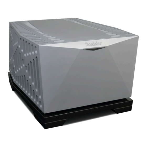
- Page 1 3060 Stereo Power Amplifier Owners Manual 3/17/2013 Boulder Amplifiers, Inc. 3235 Prairie Ave. Boulder, CO 80301 (303)449-8220 www.boulderamp.com...
-
Page 3: Thank You
Please take a few minutes to read through this owner’s manual prior to using your 3060. This will help you to understand the basic functions and outstanding capabilities of the amplifier. It will also allow you to maximize the exceptional performance for which they were designed. -
Page 5: Table Of Contents
Table of Contents Getting Started Placement of the 3060 Stereo Power Amplifier Connecting to the AC Mains Outlet Connecting to a Balanced Source Connecting to an Unbalanced Source Polarity Connecting Your Loudspeakers Operation Powering Up Input DC Offset Voltage Detection... -
Page 6: Getting Started
Exact voltage and frequency compatibility is stated in the specifications section. Once the 3060 Power Amplifier is connected to a live mains outlet and the rear panel switch is moved to the “On” position, an outline of the power button on the front panel will become illuminated and blink for a short time. - Page 7 Getting Started...
-
Page 8: Connecting To A Balanced Source
3060 Power Amplifier. The negative input (pin 3) should be wired to ground only at the RCA connector. This brings the negative input reference of the 3060 to the unbalanced source ground, thus reducing loops. Another option for accommodating unbalanced sources is that of the Boulder ABL2 Input Adapter. - Page 9 Getting Started...
-
Page 10: Polarity
Please note that the 3060 Stereo Power Amplifier conforms to the standard of pin 2 as the “high” or “hot” pin for the balanced input. The Polarity of the 3060 Stereo Power Amplifier is such that a positive-going transition at pin 2 will produce a positive-going transition at the “+”... - Page 11 Getting Started...
-
Page 12: Operation
Powering Up With all connections made, you are ready to listen to your Boulder 3060 Stereo Power Amplifier. To turn the amplifier on, slide the rear panel POWER switch to the ON position, then press the STANDBY button on the front panel. The amplifier will perform a warm up cycle and the power-button indicator will blink white and red. - Page 13 Operation...
-
Page 14: Input Dc Offset Voltage Detection
Clip Detection Clipping of the waveform results when any amplifier is driven at too high a level. A clip detection circuit is included in the 3060 Stereo Power Amplifier. The indicator will indicate clipping by momentarily turning from white to red. Both voltage and current modes of clipping will be detected, although generally it is only voltage clipping which occurs. - Page 15 Operation...
-
Page 16: Remote Control
Operation of the Boulder 3060 Stereo Power Amplifier by remote control is possible by use of a Boulder Link cable to a Boulder preamplifier. When Boulder Link is connected correctly, the 3060 will turn on and off with the preamplifier. Moreover, the Boulder 3060 is capable of issuing... - Page 17 Remote Control...
-
Page 18: Boulder Link
Setting Boulder Link Switch Every Boulder Link system must have one, and only one “MASTER” component. This is usually the preamplifier. In the case of the 3060 Power Amplifier, one channel should be set to “MASTER” if no preamplifier is connected by Boulder Link. - Page 19 Boulder Link...
-
Page 20: Setting Boulder Link Id Number
Every component is required to have a unique Boulder Link ID number. Each Boulder 3060 Stereo Power Amplifier has an amplifier ID switch on the rear panel. Start by setting the first switch to “0” or “1” by pressing either button above or below the ID window. Once the first amplifier is set, assign any other amplifiers numbers, moving up in sequence without duplication. - Page 21 Boulder Link...
-
Page 22: Boulder Link Messages
Boulder Link Boulder Link Messages Each component in the system can send a message to the preamplifier which is then shown on its display. This is particularly helpful in confirming the operation status of each power amplifier in a multiple amplifier system. - Page 23 Boulder Link...
-
Page 24: Fault Conditions
Fault Conditions Fatal Errors If the indicator of the 3060 Stereo Power Amplifier blinks white rapidly for a short time and a series of red flashes follows, a fatal error has occurred. The indicator will flash red in a specific sequence, defining its error code to an authorized Boulder technician. - Page 25 Fault Conditions...
-
Page 26: Appendix
Appendix Specifications Continuous Power, Each Channel Watts Ω THD 20-2kHz THD 20kHz 0.0008% 0.0035% 0.0009% 0.0045% 0.0014% 0.0090% Peak Power, Each Channel Watts Ω 1000 1650 2000 Equivalent Input Noise (EIN), 20kHz BW 1.5 µV Magnitude Response, 20 to 20KHz +0.00, -0.04 dB Magnitude Response, -3dB at 0.015Hz, 200kHz... - Page 27 Appendix All specifications taken at 240 VAC mains Power Weight: Amplifier: 355 lbs. (161 kg), Granite Base: 86 lbs. (39 kg), Shipping: 563 lbs. (256 kg). Amplifier Dimensions (Inches):...
-
Page 28: Troubleshooting
Appendix Troubleshooting SYMPTOM CAUSE REMEDY No Power Indication Rear Panel Power Turn on power switch switch is not on Power amplifier is not Connect to AC Mains plugged in outlet Home circuit breaker Have line voltage is tripped checked Red power indication Low line voltage Reset breakers on rear panel... - Page 29 Appendix...
-
Page 30: Notes
Appendix Notes:... - Page 31 Appendix Notes:...
Need help?
Do you have a question about the 3060 and is the answer not in the manual?
Questions and answers