
Subscribe to Our Youtube Channel
Related Manuals for Boulder 3010


Summary of Contents for Boulder 3010
- Page 1 3010 Instruction Manual 06/01/2017 Boulder Amplifiers, Inc. Rev. 1.0 255 S. Taylor Ave. Louisville, CO 80027 (303) 449-8220 www.boulderamp.com P/N: 91053...
- Page 2 About About Boulder Amplifiers, Inc. Boulder was founded in 1984 and is the last high-performance audio manufacturer operating in North America to still perform all of its own design, engineering and manufacturing in-house. While this form of production may be more costly than outsourcing, the resulting quality control and reliability of the finished products are never compromised.
-
Page 3: Thank You
Please take a few minutes to read through this instruction manual prior to using your 3010. This will help you understand the many functions and capabilities of the preamplifier. It will also allow you to maximize the convenience and performance for which it was engineered. - Page 4 • • • • • • • • • • • • • • • • • • • • • • • Connecting the 3000 Power Supply to the 3010 Chassis •...
- Page 5 Table of Contents Polarity Absolute 2-11 • • • • • • • • • • • • • • • • • • • • • • • • • • • • • • • • • • • • • • • • • • • • • • • • • • • Polarity Right Channel 2-11 •...
-
Page 6: Table Of Contents
Table of Contents Programming HTML Programming • • • • • • • • • • • • • • • • • • • • • • • • • • • • • • • • • • • • • • • • • • • • • • • • • • Page Tabs •... - Page 7 • • • • • • • • • • • • • • • • • • • • • • • • • • • • • • • • • • • • • • • • • • • • • • 3010 Preamplifier Dimensions •...
- Page 8 Introduction Introduction The 3010 embodies years of development and is the most advanced preamplifier available. Here are some of the features that set the 3010 apart from the competition: Analog features: • Separate left analog channel, right analog channel and digital power supplies in an outboard chassis.
- Page 9 Before You Start The 3010 system comes in two assemblies that must be put in place and connected: the 3010 Preamplifier and the 3000 Power Supply. You should have received a large, heavy crate. The pieces included inside the crate are: 1.
- Page 10 Boulder factory. Do not use bleach! Bleach will remove the anodized surface of the casework. Never use any type of abrasive to clean the casework. If you have any questions, please contact your authorized Boulder dealer.
-
Page 11: Placement And Installation
The 3010 should be placed at least 10 inches (25.4 cm) away from the 3010. The 3010 should not be stacked directly on top of the 3000 to allow for proper ventilation of the power supply. - Page 12 Introduction Connecting the 3000 Power Supply Your Boulder 3010 Preamplifier is supplied with a Boulder 3000 Power Supply. Each of the four internal supplies is independent of the others. The front panel LED confirms the correct operation of all four internal power supplies.
-
Page 13: Connecting The Inputs
Connecting the Inputs To get started listening, you only need to connect sources to the 3010 as you would any other preamplifier, and connect the power supply as on... -
Page 14: Connecting To An Unbalanced Source
It converts a balanced input into a RCA phono input at the rear of the 3010. Like the above cable, the negative input of the 3010 is connected to the ground of the RCA phono. However, this negative side will then share the shield wire with the chassis ground and will not have the best hum rejection. - Page 15 Connections from sources such as a CD player, DVD player, phono preamplifier, tuner, or cable/satellite receiver can be made to the analog input connections. The Ethernet connections are for Internet access to provide updates to the 3010.
- Page 16 (input) cables. With the low output impedance of the 3010, distances of more than 50 meters between preamplifier and power amplifier are practical.
- Page 17 1-GROUND Polarity Please note that the 3010 Preamplifier conforms to the standard of Pin 2 as high or “hot” for all analog balanced inputs and outputs. Because input and output polarities are handled through the Setup menu and the remote control, concern for polarity is unnecessary while connecting sources.
- Page 18 Ethernet connector on the rear panel of the 3010; it does not matter which one you use. It is possible to confirm that the 3010 is connected to a network. To do so, press the Setup button on the front panel Button Bar, then press the System Info button.
- Page 19 ON or damage may occur, even when the 3010 is in Standby mode! Always turn the unit OFF from the rear panel of the 3000 Power Supply or disconnect the AC mains power cord before disconnecting any of the DC power cables.
-
Page 20: Front Panel Controls And Screen Modes • • • • • • • • • • • • • • • • • • • • • • • • • • • • • • • •
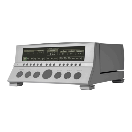
Input Trim Output 3 The 3010 also has 15 buttons on a Button Bar located between the display and the control knobs. Some of these buttons will align with various functions shown on the display. The unit will power on with the Home Screen displayed. -
Page 21: Front Panel Knob Functions
When the display is showing the Home Screen, the Center Control Knob will control the Volume of the 3010. At other times, when the 3010 is in the Option or Setup modes, the Center Control Knob will adjust other features of the 3010’s operation. - Page 22 When Input Trim is adjusted for a particular input, the 3010 will remember the adjustment for each input and automatically change the Trim Level when that input is selected.
- Page 23 Balance To change the left-to-right level balance, rotate the Balance Knob on the front panel of the 3010. “Center” will show in the Balance portion of the display. Turning the control to the right, or clockwise, will cause an indication such as “L -5.5“...
- Page 24 Front Panel Button Functions: Home Screen The 3010 has a large, centrally mounted Button Bar located between the display and control knobs. There are 15 buttons on this bar that will all correspond to various functions, depending on if the unit is showing the...
-
Page 25: Inputs 1-6 • • • • • • • • • • • • • • • • • • • • • • • • • • • • • • • • • • • • • • • • • • • • • • • • • • • • • • • • •
Operation Inputs 1 - 6 The 3010 has six inputs. Each of these inputs can be directly selected by pressing the button that corresponds with the input you wish to select. To select an input, press one of the push buttons labeled Input 1 through Input 6 on the front panel Button Bar. -
Page 26: Mute • • • • • • • • • • • • • • • • • • • • • • • • • • • • • • • • • • • • • • • • • • • • • • • • • • • • • • • • • • • • • •
Knob to the left (counter-clockwise) will decrease the volume setting even though the output will remain muted. Rotating the Center Control Knob to the right (clockwise) will immediately bring the 3010 out of Mute mode. The function of the Mute button in the center of the Button Bar will always remain the same, regardless of screen mode. -
Page 27: Option • • • • • • • • • • • • • • • • • • • • • • • • • • • • • • • • • • • • • • • • • • • • • • • • • • • • • • • • • • • •
Home Screen by pressing any button on the front panel Button Bar. Mute Output 1, 2, and 3 The 3010 has three Main Outputs. Each Main Output can be muted individually by pressing the Mute Output 1, Mute Output 2, or Mute Output 3 button on the Button Bar. -
Page 28: Standby • • • • • • • • • • • • • • • • • • • • • • • • • • • • • • • • • • • • • • • • • • • • • • • • • • • • • • • • • • •
Standby mode, it is only necessary to place the unit in Standby when not in use. You do not need to turn the 3010 off via the Master AC switch on the rear panel of the 3000 Power Supply. The 3010 was designed for years of operation in this manner and no damage to the unit will occur. -
Page 29: Polarity Output 1, 2 And 3 • • • • • • • • • • • • • • • • • • • • • • • • • • • • • • • • • • • • • • • • • • •
“polarity” is used to indicate 180° phase change, or inversion, as available in the 3010 Preamplifier. The 3010 has three Main Outputs. The polarity of each Main Output can be changed individually by pressing the Polarity Output 1, Polarity Output 2, or Polarity Output 3 button on the Button Bar while in Option mode. - Page 30 0 to 360 degrees. The term “polarity” is used to indicate 180° phase change, or inversion, as available in the 3010 Preamplifier. The polarity of all active Main Outputs can be changed simultaneously by pressing the Polarity Absolute button on the Button Bar while in Option mode.
-
Page 31: Front Panel Control: Setup Screen
Operation The polarity of only the right channel of all Main Outputs can be changed simultaneously by pressing the Polarity Right Channel button on the Button Bar while in Option mode and an inverted polarity icon ( ) will appear in the corresponding output box. This can be useful when trying to determine if a speaker cable, interconnect cable, or phono leads may be wired incorrectly within the system. -
Page 32: Input Polarity
Operation Input Balance The screen will show a box reading Input Balance on the left side of the display and a box showing the Input Balance level on the right side of the screen. To adjust the Input Balance, rotate the Center Control Knob to the left or right until the desired balance offset is obtained as indicated in the display. -
Page 33: Input Theater/Record • • • • • • • • • • • • • • • • • • • • • • • • • • • • • • • • • • • • • • • • • • • • • •
WARNING: Theater Mode should be used with extreme caution, as there is no way to control the volume of the 3010 while in Theater Mode! If it is programmed for an input that does not have externally controlled volume, damage to speakers or other components may occur! WARNING: If the input is programmed for “THEATER MODE,”... -
Page 34: Input Recordable • • • • • • • • • • • • • • • • • • • • • • • • • • • • • • • • • • • • • • • • • • • • • • • • • •
Operation The screen will show a box reading Input Theater Mode on the left side of the display and a box showing On or Off on the right side of the screen. To set an input to Theater Mode, rotate the Center Control Knob to the right (clockwise) until the box on the right side of the display reads, “On.”... -
Page 35: Input Off • • • • • • • • • • • • • • • • • • • • • • • • • • • • • • • • • • • • • • • • • • • • • • • • • • • • • • • • • •
Operation Input Off While in Setup mode, pressing the Input Off button will allow you to temporarily disable an input so that it cannot be selected from the front panel or the remote control. To disable an input, press the button to select the Input you wish to disable. -
Page 36: Aux Polarity • • • • • • • • • • • • • • • • • • • • • • • • • • • • • • • • • • • • • • • • • • • • • • • • • • • • •
(clockwise) to configure the polarity as Pin 3 Hot. Rotate the Center Control Knob to the left (counter-clockwise) to configure the Aux Polarity as Pin 2 Hot. When programming the Auxiliary Output Polarity, the 3010 will change the Output On or Off simultaneously with the display. -
Page 37: Soft Level • • • • • • • • • • • • • • • • • • • • • • • • • • • • • • • • • • • • • • • • • • • • • • • • • • • • • • • •
Center Control Knob to the right (clockwise) to turn the Auxiliary Output On. Rotate the Center Control Knob to the left (counter-clockwise) to turn the Auxiliary Output Off. When programming the Auxiliary Output, the 3010 will change the output On or Off simultaneously with the display. -
Page 38: Output Polarity • • • • • • • • • • • • • • • • • • • • • • • • • • • • • • • • • • • • • • • • • • • • • • • • • • • •
0 to 360 degrees. The term “polarity” is used to indicate 180° phase change, or inversion, as available in the 3010 Preamplifier. To configure the polarity of each output, press the Output Polarity button while in Setup mode. - Page 39 “-100 to 0” to “0 to 100” or anywhere in between. This feature allows you to set the volume control of the 3010 to the scale of your choice. For example, one possibility would be to set the scale to “-80 TO 20”...
-
Page 40: Volume Default/Max • • • • • • • • • • • • • • • • • • • • • • • • • • • • • • • • • • • • • • • • • • • • • • •
The factory setting for the 3010’s volume default adjustment is “Off.” The volume control does not have a maximum volume setting from the factory. - Page 41 This feature allows you to set the volume of the 3010 to the programmed default level of your choice. For example, setting the Volume Default level at -60.0 dB will cause the 3010 to always set the volume at -60.0 dB when coming out of Standby.
-
Page 42: System Info • • • • • • • • • • • • • • • • • • • • • • • • • • • • • • • • • • • • • • • • • • • • • • • • • • • • • • •
It is permanent and cannot be changed by the user. IP Address: If the 3010 is attached to an active network, the IP address of the unit will be indicated here. This is useful when accessing the HTML page for programming. -
Page 43: Return To Home • • • • • • • • • • • • • • • • • • • • • • • • • • • • • • • • • • • • • • • • • • • • • • • • • • •
If you encounter problems where the IR remote control interferes with the operation of other electronic devices in your home, you will need to change the remote address in the 3010 and in the handheld remote control. To change the Remote Address, press the Remote Address button in the center of the Button Bar while on the System Info screen in Setup mode. -
Page 44: Restore Factory Defaults • • • • • • • • • • • • • • • • • • • • • • • • • • • • • • • • • • • • • • • • • • •
Restore Factory Defaults button. To restore the 3010 to the original factory default settings, press the Setup button, followed by the Restore Factory Defaults button. The front panel display will show “Restore Factory Defaults?” To restore the 3010 to the original factory settings, press the Restore button. - Page 46 Remote Control Remote Control The 3010’s handheld remote control can be used to control all of the preamplifier’s functions. Most of the buttons on the remote control will have the same function as the buttons on the front panel of the 3010.
- Page 47 To replace the batteries in the remote control, use a 7/64” hex (Allen) screwdriver to remove the four screws that secure both halves of the remote. This type of screwdriver is included in the 3010 Accessory Kit. The battery type is a CR2032 “coin” style battery. Insert the tip of a 1/8”...
- Page 48 Remote Control Carefully pry the battery out of the holder. Repeat the process for the second battery. CAUTION: The batteries must be installed at an angle and care must be taken not to bend the battery holder’s electrical contacts or damage to the remote control may occur! When installing the new battery, insert it at an angle that presses against the positive (+) terminals first.
- Page 49 “ON” position. To select ID 6, all switches must be in the “OFF” position. To Change the Remote Address for the 3010: 1. Press the Setup button, then press the System Info button. 2. Press the Remote Address button.
- Page 50 Standby mode, it is only necessary to place the unit in Standby when not in use. You do not need to turn the 3010 off via the Master AC switch on the rear panel of the power supply. The 3010 was designed for years of operation in this manner, so that no damage to the unit will occur.
- Page 51 Remote Control While in Soft mode, the level of all three Main Outputs on both channels will be reduced to the current volume setting plus the amount programmed into the Soft function. Mute To completely mute the volume (infinite attenuation), press the MUTE button.
- Page 52 Remote Control When the brightness is set to low levels, the screen will temporarily go two steps brighter than the programmed display brightness setting for five seconds, when any button is pressed on the front panel or remote control, and then return to the desired brightness. This ensures that if a function is changed, it will be noticed whether intentional or inadvertent.
- Page 53 Remote Control Button Functions and Use: Back Blend More and Blend Less The Blend buttons adjust the 3010’s output from wide stereo separation output to mono output. This may be useful when listening to recordings with images that are hard-panned to one channel or when listening to monaural phono recordings.
- Page 54 Remote Control To increase the level of an input relative to the others, press the Input Trim Up button ( To decrease the level of an input relative to the others, press the Input Trim Down button ( Outputs 1 – 3: Up, Down, and Mute Each of the three outputs can be adjusted for output level Up or Down or Mute.
-
Page 56: Html Programming
To access the 3010’s HTML page, you will need a computer that is connected to the same network as the 3010. To find the HTML page IP address, press the Setup button, followed by the System Info button. You will see a list of information about the 3010, including: Serial Number:... -
Page 57: Page Tabs
Page Tabs The HTML screen is divided into four tabbed pages: Main Page, Options, Setup and Boulder Net. The tabs for these pages can be found in the upper left-hand corner of the HTML screen. Clicking on each tab will present a different set of control options. -
Page 58: Mute
There are two checkboxes on the Main Page, Mute and Soft. Mute It is possible to Mute the outputs so that the 3010’s outputs are reduced to infinite attenuation. To mute the outputs, click on and mark the checkbox marked Mute. -
Page 59: Soft
60dB from its current level when “Soft Mute” is engaged. Blend The Blend Slider adjusts the 3010’s output from wide stereo separation to mono output. This may be useful when listening to recordings with images that are hard-panned to one channel or when listening to monaural phono recordings with a stereo phono cartridge. -
Page 60: Balance • • • • • • • • • • • • • • • • • • • • • • • • • • • • • • • • • • • • • • • • • • • • • • • • • • • • • • • • • • •
Programming To increase the level of Blend, click on the Blend Slider and move it to the right. An indication such as “-12” will appear in the Blend Box on the front panel display. To decrease the level of Blend, click on the Blend Slider and move it to the left. -
Page 61: Inputs
Programming Inputs Inputs 1 – 6 are grouped in a blue Input Bar, with each input occupying a button within the bar. To select an input, click on the button for the desired input. When an input is selected for listening, the box color for that input dark blue. -
Page 62: Outputs
Programming It is possible to temporarily disable an input. To do so, click on the desired input and then click on the box marked Off. The box will turn dark blue. The selected input will now be disabled. To enable an input, click on the desired input and then click on the box marked Off. -
Page 63: Mute
To bring the 3010 out of Standby mode, click on the button marked Standby again. Upload Logs The 3010 keeps a running log of errors and system crashes. At times it may be useful to send these logs to the Boulder factory to help eliminate... -
Page 64: Version
The serial number of the 3010 will be indicated here. It cannot be changed. Options Mute It is possible to Mute the outputs so that the 3010’s outputs are reduced to infinite attenuation. To mute the outputs, click on and mark the checkbox marked Mute. -
Page 65: Aux Select
Programming Aux Select Inputs 1 – 6 are grouped in a blue bar, with each input occupying a button within the bar. To select an input to route to the Auxiliary Output, click on the box for the desired input. When an input is selected, the button color dark blue for that input will change to and that the audio from that input will... -
Page 66: Polarity
“polarity” is used to indicate 180° phase change, or inversion, as available in the 3010 Preamplifier. Each output of the 3010 defaults to Pin 2 “High” or hot. The Output Polarity checkbox will allow you to invert the polarity of an individual output to compensate for amplification in an independent zone or to test the polarity of each portion of a bi- or tri-amplified system. -
Page 67: Polarity Right Channel
0 to 360 degrees. The term “polarity” is used to indicate 180° phase change, or inversion, as available 51 in the 3010 Preamplifier. It is possible to invert the polarity of only the right channel of all enabled Main Outputs. -
Page 68: Setup
Click on the Name box and type the new input name you would like within the box, then click on the button marked Set Name. The new name will now appear on the 3010’s front panel display. It is possible to rename all of the 3010’s inputs this way. -
Page 69: Polarity
Polarity Each input of the 3010 defaults to Pin 2 “High” or hot. The Polarity checkbox will allow you to invert the polarity of an input to compensate for a source with inverted output. -
Page 70: Recordable
Programming 3010 to be easily integrated into a surround sound or theater system. Theater Mode is only intended to be used with a surround sound processor. When operating in Theater Mode the 3010’s Volume Control, Input Trim, Input Balance, Balance and Output Trim are disabled. -
Page 71: Outputs
Type the new output name you would like in the box and then click on the button marked Set Name. The new name will now appear on the 3010’s Home Screen. It is possible to rename all of the 3010’s outputs this way. -
Page 72: Volume Resolution
For example, setting the Default Volume level of -60.0 dB will cause the 3010 to always set the volume at -60.0 dB when coming out of Standby. To enter the Default Volume, click on the Default Volume slider and move the slider until the desired Default Volume setting is indicated under the left side of the Default Volume slider. -
Page 73: Max Volume • • • • • • • • • • • • • • • • • • • • • • • • • • • • • • • • • • • • • • • • • • • • • • • • • • • • •
Programming Max Volume The maximum allowable volume setting can be programmed to prevent children or other users from turning the system up too loud. Settings in 1.0 dB steps from -100.0 dB to 0.0 dB or anywhere in between can be entered. -
Page 74: Settings
“polarity” is used to indicate 180° phase change, or inversion, as available in the 3010 Preamplifier. The Auxiliary output of the 3010 defaults to Pin 2 “High” or hot. The Aux Polarity checkbox will allow you to invert the polarity of the Auxiliary output to compensate for a connected device that inverts polarity. -
Page 75: Restore Factory Defaults • • • • • • • • • • • • • • • • • • • • • • • • • • • • • • • • • • • • • • • • • •
It is possible to restore all programming to the original, factory default settings by pressing the Reset Factory Defaults button. To restore the 3010 to the original factory default settings, click on the Restore Factory Defaults button. The 3010 will immediately restore the original factory settings. - Page 76 Recording Recording Connecting a Recording Device A recording device can easily be connected to the Boulder 3010 Preamplifier. One output labeled “AUX OUT” is provided on the rear panel of each ording channel. Connect these to the inputs of your recording device.
-
Page 77: Programming For Recording
Recording Programming for Recording Instead of having hardware-dedicated inputs for playback (tape) monitors, any input may be chosen for this purpose through software selection. Connect the outputs of these recorders to any input you have chosen in the previous section. To program the selected input for recording, press the Setup button on the front panel Button Bar, followed by two presses of the Input Theater/ Record button. -
Page 78: Technical Specifications
Power Consumption 240W Max All specifications taken at 240 VAC mains Power Weights and Dimensions 3010 Preamplifier Chassis: 19”W x 18”D x 9.25”H (78lbs.) 3000 Power Supply Chassis: 19”W x 18”D x 5.1”H (45 lbs.) Shipping (Preamp + Power Supply):... - Page 79 Appendix 3010 Preamplifier Dimensions 18.255 18.050 5.120 18.255 18.050 TOP VIEW SCALE 1 : 2 5.120 19.150 19.000 TOP VIEW SCALE 1 : 2 19.150 14.855 19.000 2.000 FRONT VIEW SCALE 1 : 2 9.250 8.800 14.855 .975 2.000 12.920 .600...
- Page 80 Appendix 3000 Power Supply Dimensions 18.210 17.750 18.210 17.750 17.750 TOP VIEW SCALE 1 : 2 19.000 TOP VIEW SCALE 1 : 2 5.050 19.000 14.855 2.000 2.145 FRONT VIEW 5.050 SCALE 1 : 2 5.050 14.855 2.000 2.145 .975 .550 12.920 FRONT VIEW...
-
Page 81: Troubleshooting
Appendix Troubleshooting SYMPTOM CAUSE REMEDY No Power Rear panel power Turn on power Indication switch is not on switch Preamplifier is not Connect to an AC plugged in Mains outlet Home circuit Have line voltage breaker is tripped checked Red power Low line voltage Reset breakers on indication... - Page 82 Appendix Notes:...
- Page 83 Appendix Notes:...
Need help?
Do you have a question about the 3010 and is the answer not in the manual?
Questions and answers