Table of Contents
Advertisement
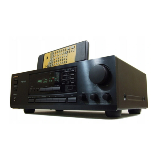
Audio Video Control Receiver
TX-SV353
Instruction Manual
SYSTEM
DOLBY SURROUND
P R O
•
L O G I C
ON
OFF
SPEAKERS A
STAND-BY
SPEAKERS B
TUNING
SURROUND
CENTER
DOWN
MODE
MODE
DELAY TIME
PHONES
VIDEO
/ 1
VDP
VIDEO
/ 2
VCR
TV/AUX
TAPE(MONITOR)
Thank you for purchasing the Onkyo Audio Video
Control Receiver.
Please read this manual thoroughly before making
connections and turning on the power.
Following the instructions in this manual will enable
you to obtain optimum performance and listening
enjoyment from your new Audio Video Control
Receiver.
Please retain this manual for future reference.
MASTER VOLUME
1
2
3
4
5
6
7
8
9
GROUP
0/10
SCAN
UP
DIRECT TUNING
MEMORY FM MUTE / MODE
MIN
MAX
CLEAR
BASS
TREBLE
BALANCE
FM
AM
PHONO
C D
L
R
TX-SV
353
AUDIO VIDEO CONTROL RECEIVER
Contents
Before using
Important safeguards ........................ 2
Precautions ....................................... 3
Features............................................. 4
Supplied accessories......................... 4
Before operating this unit ................. 5
Preparation
Connecting audio equipment............ 6
Connecting video equipment............ 7
Connecting speakers......................... 8
Positioning speakers ......................... 9
Connecting the power....................... 9
Connecting antennas....................... 10
Operation
Tuning in a radio station................. 14
Using preset radio stations.............. 15
Selecting a Surround mode............. 16
Recording a source ......................... 19
Using TAPE (MONITOR) Button ... 20
codes ............................................ 21
A few important notes
Troubleshooting guide.................... 24
Specifications ................................. 25
Control positions and names .......... 26
Remote controller RC-383M.......... 27
Advertisement
Table of Contents

Related Manuals for Onkyo TX-SV353


Summary of Contents for Onkyo TX-SV353
-
Page 1: Table Of Contents
A few important notes Troubleshooting guide....24 Specifications ......... 25 Control positions and names ..26 Thank you for purchasing the Onkyo Audio Video Remote controller RC-383M..27 Control Receiver. Please read this manual thoroughly before making connections and turning on the power. -
Page 2: Important Safeguards
“WARNING” WARNING AVIS “TO REDUCE THE RISK OF FIRE OR ELECTRIC SHOCK, RISK OF ELECTRIC SHOCK RISQUE DE CHOC ELECTRIQUE DO NOT EXPOSE THIS APPLIANCE TO RAIN OR MOIS- DO NOT OPEN NE PAS OUVRIR TURE.” The lightning flash with arrowhead symbol, within CAUTION: an equilateral triangle, is intended to alert the user to the presence of uninsulated “dangerous voltage”... -
Page 3: Precautions
The fuse is located inside the chassis and is not user-serviceable. CAUTION: TO PREVENT ELECTRIC SHOCK, MATCH If power does not come on, contact your Onkyo authorized service WIDE BLADE OF PLUG TO WIDE SLOT, FULLY INSERT. station. Sur les modèles dont la fiche est polarisée. -
Page 4: Features
Features Supplied accessories Power output: Check that the following accessories are supplied with this unit. The number of each supplied accessory is indicated in parenthe- European models: ses. Stereo mode 2 60 watts at 6 ohms (DIN) Surround mode Front L/R and Center Channels 3 50 watts at 6 ohms (DIN) Rear Channels (Rear channel only driven) 15 watts + 15 watts at 6 ohms (DIN) -
Page 5: Before Operating This Unit
5 m mately six months, depending on the (16 feet) frequency of use. The TX-SV353 comes equipped with two AA (R6 or UM-3) manganese bat- teries, but we recommend that long-life AA (LR6 or AM-3) size alkaline batter- ies be used when replacing the batteries. -
Page 6: Connecting Audio Equipment
When you operate the desired component (compact disc player or tape deck), The TX-SV353 Input Selector automat- ically switches to that component. In this way, it is not necessary to operate the Input Selector... -
Page 7: Connecting Video Equipment
ARE TRADEMARKS OF DOLBY LABORATORIES AC OUTLETS REMOTE OUTPUT INPUT OUTPUT INPUT LICENSING CORPORATION. CONTROL SWITCHED TOTAL 100W MAX. FRONT SPEAKERS AUDIO VIDEO CONTROL RECEIVER TX-SV353 MODEL NO. OUTPUT INPUT RATING: SUB- (REC) (PLAY) INPUT OUTPUT INPUT WOOFER PRE OUT VOLTAGE SELECTOR... -
Page 8: Connecting Speakers
Connecting speakers Please connect each speaker according to the illustration, observing the correct connections for R, L, + and –. Do not use unnecessarily long or extremely thin speaker cables. If the DC resistance of the speaker cables is too high, the damping factor will decrease, adversely affecting the sound quality. -
Page 9: Positioning Speakers
(the display is lit). TX-SV AUDIO VIDEO CONTROL RECEIVER Pressing the SYSTEM switch on the TX-SV353 to set it to OFF turns off the unit. (When the SYSTEM switch is set to OFF, only a small amount of power is used.) -
Page 10: Connecting Antennas
FM and TV (or VCR) signals can inter- fere with each other. If you must use a common FM/TV (or VCR) antenna, use a directional linkage type splitter. Directional linkage type splitter To TX-SV353 To TV (or VCR) - Page 11 Connecting antennas Connecting the included antennas Connecting the T-shaped FM antenna: The T-shaped FM antenna is for indoor use only. Extend the antenna and move it in various directions until the clearest ANTENNA signal is received. Fix it with push pins or similar imple- ments in the position that will cause the least amount of dis- tortion.
-
Page 12: Listening To Your Favorite Source
Listening to your favorite source Basic operations 1. Press the SPEAKERS A button. SPEAKERS A indicator lights up. 2. Press the desired input selector button (e.g. PHONO). MASTER VOLUME SYSTEM The appropriate letters (e.g. PHONO) appear on the display. DOLBY SURROUND P R O •... - Page 13 The sleep timer can power off the system after a specified time period. To operate this function, use the remote controller supplied with your TX-SV353. 1. Start playing the source to which you would like to listen (CD, tape or radio broadcast).
-
Page 14: Tuning In A Radio Station
Tuning in a radio station DOWN TUNING DIRECT TUNING MASTER VOLUME SYSTEM Number buttons DOLBY SURROUND P R O • L O G I C SPEAKERS A GROUP 0/10 SCAN STAND-BY SPEAKERS B TUNING SURROUND CENTER DOWN DIRECT TUNING MODE MODE DELAY TIME MEMORY FM MUTE / MODE... -
Page 15: Using Preset Radio Stations
Using preset radio stations Number buttons GROUP SCAN SENDING/ LEARNED SEND LEARN POWER SLEEP GROUP INPUT SELECTOR MULTI-CH TV/AUX VIDEO-1 VIDEO-2 INPUT MASTER VOLUME TAPE TUNER PHONO PROGRAMMABLE AREA TV/VIDEO SYSTEM POWER POWER DOLBY SURROUND P R O • L O G I C DECK-A DECK-B TUNER... -
Page 16: Selecting A Surround Mode
Surround system Since the TX-SV353 is equipped with a front amplifier, center amplifier, and a rear (surround) amplifier, all Dolby Pro Logic Surround effects can be produced. When using video cassette tapes or video discs that have the DOLBY STEREO or DOLBY SURROUND trade mark, you can enjoy the feeling of a movie theater in your own room. - Page 17 Selecting a Surround mode SENDING/ Surround Mode SEND LEARN LEARNED POWER SLEEP Select a mode by pressing the SURROUND MODE button. INPUT SELECTOR MULTI-CH TV/AUX VIDEO-1 VIDEO-2 INPUT Make your choice of modes depending on the type of music you TAPE TUNER PHONO...
- Page 18 Selecting a Surround mode SENDING/ SEND LEARN LEARNED MASTER VOLUME POWER SLEEP INPUT SELECTOR MULTI-CH TV/AUX VIDEO-1 VIDEO-2 INPUT SYSTEM TAPE TUNER PHONO DOLBY SURROUND P R O • L O G I C PROGRAMMABLE AREA TV/VIDEO POWER SPEAKERS A GROUP 0/10 SCAN...
-
Page 19: Audio Video Control Receiver Tx-Sv
Recording a source Recording an audio source Please read the instruction manuals con- MASTER VOLUME cerning the operation of each unit. SYSTEM DOLBY SURROUND 1. Insert a blank tape into the tape deck. P R O • L O G I C SPEAKERS A GROUP 0/10... -
Page 20: Using Tape (Monitor) Button
Using TAPE (MONITOR) Button Using a graphic equalizer Connect the graphic equalizer to the TAPE VIDEO-1/VDP VIDEO-2/VCR TV/AUX TAPE(MONITOR) PHONO jacks on the rear panel. If a tape deck is used, connect it to the tape jacks on the graphic equalizer. While pressing the button for the source that you wish to equalize and listen to, press the TAPE (MONITOR) button. -
Page 21: Programming Remote Controller Codes
If you are using another manufacturer’s product that has a remote controller, you can memorize that component’s codes into the RC-383M. NOTE: • The commands of Onkyo cassette tape decks and the CD player are already stored at the DECK-A, DECK-B, and CD positions of the remote controller. - Page 22 Programming remote controller codes Leaning new controller codes 1. Set the SEND/LEARN selector switch to LEARN. 2. Place the head of your old remote controller 2-4 inches (5-10 cm) from the head of the RC-383M, lay- SENDING/ SEND LEARN LEARNED ing both units on a table or a flat surface.
- Page 23 MEMO...
-
Page 24: Troubleshooting Guide
AC plug from the outlet and then plug it again. AC fuse blown. Contact your Onkyo Service Center. Power on but no sound. indicator is lit. While pressing the input selector button for the TAPE MON. -
Page 25: Specifications
Specifications AMPLIFIER SECTION TUNER SECTION Continuous Power output (DIN) Front L/R Channels: 60 W 2 at 6 ohms Tuning Range: Center Channel: 60 W at 6 ohms 87.5 — 108.0 MHz (100 kHz steps) Rear L/R Channels: 15 W 2 at 6 ohms 87.50 —... -
Page 26: Control Positions And Names
Control positions and names MASTER VOLUME SYSTEM DOLBY SURROUND P R O • L O G I C SPEAKERS A GROUP 0/10 SCAN STAND-BY SPEAKERS B DOWN TUNING DIRECT TUNING SURROUND CENTER MODE MODE DELAY TIME MEMORY FM MUTE / MODE CLEAR BASS TREBLE... -
Page 27: Remote Controller Rc-383M
TEST H CD operation buttons [6] TONE These buttons are used to operate an ONKYO CD player that CH SEL bears the terminal. I Test tone button (TEST TONE) [16, 17] VOLUME... - Page 28 Tel: 201-825-7950 Fax: 201-825-8150 E-mail: onkyo@onkyousa.com ONKYO EUROPE ELECTRONICS GmbH Industriestrasse 20, 82110 Germering, GERMANY Tel: 089 84 93 20 Fax: 089 84 93 226 E-mail: info@onkyo.de ONKYO EUROPE FRANCE BRANCH Domaine Technologique de Saclay 4, Rue René Razel, SACLAY-91892...
Need help?
Do you have a question about the TX-SV353 and is the answer not in the manual?
Questions and answers