Table of Contents
Advertisement
Quick Links
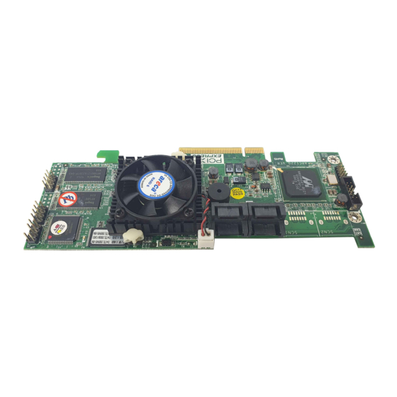
ARC-1110/1120/1130/1160/1170
( 4/8/12/16/24-port PCI-X SATA RAID Adapter )
ARC-1110ML/1120ML/1130ML/1160ML
( 4/8-port Infinband connector and 12/16-port Multi-lane
connector PCI-X SATA RAID Adapter )
ARC-1210/1220/1230/1260/1280
( 4/8/12/16/24-port PCI-Express SATA RAID Adapter )
ARC-1230ML/1260ML/1280ML
(12/16/24-port PCI-Express SATA RAID Adapter)
USER Manual
Version: 3.2
Issue Date: August, 2006
SATA RAID Cards
Advertisement
Table of Contents


Need help?
Do you have a question about the ARC-1110 and is the answer not in the manual?
Questions and answers