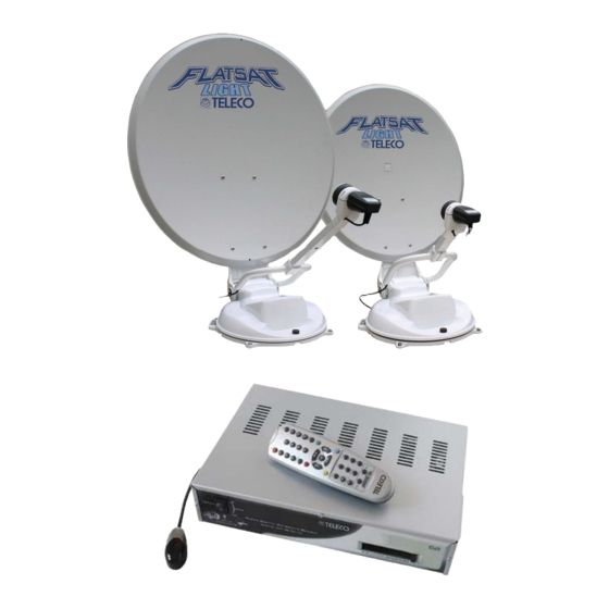
Teleco Flat Sat Light Installation Manual And User's Manual
Hide thumbs
Also See for Flat Sat Light:
- Installation manual and user's manual (28 pages) ,
- Installation and operation manual (32 pages)
Table of Contents
Advertisement
Advertisement
Table of Contents

Subscribe to Our Youtube Channel
Related Manuals for Teleco Flat Sat Light


Summary of Contents for Teleco Flat Sat Light
- Page 1 INSTALLATION GUIDE AND USER MANUAL OF THE FLAT SAT LIGHT Vers. 001...
-
Page 2: Table Of Contents
Installation with cables led through the middle of the base ..........10 Installation with lateral cable output ................12 Connections ........................13 User manual Flat Sat Light Operation System .............. 16 Satellite seeking ......................16 Programme seeking ....................... 16 Antenna lowering ......................16 Additional operations ...................... - Page 3 Language configuration ....................52 Access control ........................ 53 Modifying the PIN code ....................53 Information system ......................54 Conditioned access ......................54 Reinstalling your receiver ....................57 Introduction ........................57 Re-installation sequence ....................57 Glossary ........................... 62 Vers. 001 Flat Sat Light...
-
Page 4: Information
Technical assistance: 899.899.856 TELECO s.p.a. shall not be held responsible for any errors in drawing up this manual. All information which is contained herein is updated on the date of issue and the aforementioned revisions. TELECO s.p.a. reserves the right to make modifications according to technological changes. -
Page 5: Technical Specifications
One S-VHS output Aux audio output RS232 port for software update and service list management. Software can be updated via satellite. DataPort for connection with other TELECO devices. Technical specifications Tuner F IEC169-24 female connector Working frequency 950 2150 MHz Rated input impedance 75 Acceptable signal level from –25 to –65 dBm. -
Page 6: Searching Time
To be stored at a relative humidity of 5 - 95 % (not condensable) List of Accessories Flat Sat Light is delivered inside a cardboard case that has been specially made to protect it from knocks and pressure. The following accessories are supplied:... -
Page 7: Important Notice
Important notice Due to transport reasons, Flat Sat Light comes packaged in two separate cartons: a) The first item contains the driving unit with all the cables and the control unit. b) the second item only contains the dish. It is essential to check that the dish has not been damaged during transport when the package is opened. -
Page 8: Assembly Instructions
5) Secure the dish to the mast and screw down the four supplied screws. 6) Press the " DOWN " button in the remote control and lower the antenna. 7) Disconnect the Control unit, the battery and install Flat Sat Light on the vehicle. Assembly instructions... - Page 9 8) Fasten the Base Plate to the roof (short side towards the driving direction of the vehicle), now fasten the external powered unit to the four stud bolts of the plate, using the four nuts supplied with the equipment. Vers. 001 Flat Sat Light...
-
Page 10: Installation With Cables Led Through The Middle Of The Base
THERMORETRACTILE TUBE (Fig. 7). WARNING While performing this operation, do not pull forcefully on the cables coming from the middle of the outside unit, in order not to risk pulling them out. Vers. 001 Flat Sat Light... - Page 11 Coat both the base plate and the driving unit bottom (Fig. 10) with a thick layer of silicone to prevent any water infiltration. Screw in the four supplied nuts at the screws and tighten as required (Fig. 11). Vers. 001 Flat Sat Light...
-
Page 12: Installation With Lateral Cable Output
14) Fit the cables into a raceway up to the point where the cables enter the vehicle Fig. 15) Carefully seal the hole where the cables pass into the vehicle to prevent water from coming in. Fig. 14. Vers. 001 Flat Sat Light... -
Page 13: Connections
+ 12 Vdc voltage, which will automatically lower the antenna and lock all functions of the Control Unit simultaneously (Fig.15). Any connection made in points other than as indicated (e.g. on the alternator) can give rise to equipment malfunction and/or damage resulting in loss of the warranty. Vers. 001 Flat Sat Light... - Page 14 20) Insert one end of the SCART cable in the TV connector of the Control Unit and connect the other end to the TV set (Fig. 16) Digital receiver – to television connection 21) Inside the Control Unit are: a) Control ELECTRONICS of the outdoor unit motors. b) DVB Digital Receiver. Vers. 001 Flat Sat Light...
- Page 15 The power supply cable must come directly from the battery and be of a minimum cross- section of 5 sq.mm. Only the Flat Sat Light must be connected to this cable; all the other devices must be connected to another power supply cable.
-
Page 16: User Manual Flat Sat Light Operation System
Flat Sat Light will then search for the next satellite and store the corresponding antenna position. -
Page 17: Additional Operations
Control unit being switched off which would make satellite searching ineffective. 3) In the event that Flat Sat Light does not find the selected satellite, it will stop the antenna at the end of its stroke (either all the way out or all the way in) and show the message "... -
Page 18: Important Information
2) It is also important to know that satellites do not transmit with the same intensity throughout Europe, so if you are outside the reception area, your Flat Sat Light search might be unsuccessful. The reception areas for each Satellite can be found on the main magazines dealing in this line of business. -
Page 19: Tips On The Best Use
2) In case of snow or ice actuating the Flat Sat Light free it in order to avoid wasting battery power in order to lift it. -
Page 20: Digital Receiver
DIGITAL RECEIVER BUILT IN THE CONTROL UNIT Remote Control ON / OFF Mute TV/RADIO Numerical keys Right, left, up, down and OK keys Menu Exit Page + Audio Favourites list Info Page - Pause STOP DOWN Vers. 001 Flat Sat Light... - Page 21 Page + / - Goes to next or previous page on a list. Mute Audio service disabled DOWN Lowers the antenna and turns the system off STOP Stops the antenna and the channel search temporarily Vers. 001 Flat Sat Light...
-
Page 22: Front View
CAM modules (2) On/off Display Rear view Power supply Fuse Audio Antenna VCR (4) (13) outputs input (9) (12) input (1) Motor Unit (14) output (8) output (2) Computer S-VHS DataPort Remote port (3) (11) (10) Vers. 001 Flat Sat Light... - Page 23 Remote control IR sensor connector DataPort DataPort connector for additional devices 12V Power 12 Volt power connector. supply Fuse Fuse 10 A Motor Unit Connector where you must connect the cable coming from the external unit motors Vers. 001 Flat Sat Light...
-
Page 24: Information About Safety
Always observe safety information with the utmost care. Electronic devices on the Flat Sat Light receiver can generate potentially dangerous voltages. Electronic device covers must only be removed for maintenance and set- up purposes and only after taking all the required precautions. -
Page 25: Installation Tips
Warning: do NOT install the remote infrared sensor near fluorescent lighting or strong electrical fields as they can reduce the capacity of the sensor to capture signals emitted by the remote control. Vers. 001 Flat Sat Light... -
Page 26: Connecting To The Power Supply
(7). Using a RCA-RCA lead, the digital audio signal can be sent to an amplifier or Home Theatre system: this raises the audio on the received service to CD-level quality. Vers. 001 Flat Sat Light... -
Page 27: Immediate Use Of The Receiver
Duration of event (where available) Icons showing details of the event and service being broadcast, any Teletext, language, access control. The info banner disappears after a few seconds to provide an unhindered view of the screen. Vers. 001 Flat Sat Light... -
Page 28: Changing Service
To enjoy the service, once it has been selected, press the OK key. To exit without enjoying any service, press the EXIT key. To access the main menu, press the MENU key. Vers. 001 Flat Sat Light... -
Page 29: Favourites Lists Which Were Factory-Loaded
When viewing a service you can access several other immediate functions that allow you to modify receiver operation. Some of these - such as volume control and the MUTE function - act directly on the service being watched: Vers. 001 Flat Sat Light... - Page 30 To choose the desired audio service, use the right/left arrow keys then press OK to confirm. To exit without selecting any service, press the EXIT key. Vers. 001 Flat Sat Light...
-
Page 31: Menu And Advanced Functions
To access the main menu just press the MENU key on the remote control: To select an item from the list, use: the arrow keys to move up and down the OK key to confirm your choice the EXIT key to leave the menu. Vers. 001 Flat Sat Light... -
Page 32: The Favourites List
Use the right-left keys to move along the string To reach this screen page select the following in sequence: - Main Menu - Favourites list - Creating the list Figure 11 – Creating a list Vers. 001 Flat Sat Light... - Page 33 List type - All Services - in the list all services are marked as ON - None - in the list all services are marked as OFF Vers. 001 Flat Sat Light...
-
Page 34: Modifying A List
- Modifying a list Figure 12 – Modifying a list To choose the list you wish to modify press the TV/Radio key (selects TV or Radio service lists) or the FAV key (selects favourites lists). Vers. 001 Flat Sat Light... - Page 35 Menu or Full Screen display). When the service is Off, it cannot be used under the normal navigation modes, but it is inside the list which can be customized. Figure 12 A – Modifying a list Vers. 001 Flat Sat Light...
- Page 36 Deleting a service will remove such service completely from the list. To exit without saving the changes press EXIT To save the changes made in the list you must always press the OK key Vers. 001 Flat Sat Light...
-
Page 37: Deleting A List
ATTENTION as some parameters can limit or prevent proper operation of the receiver. This sub-menu takes you to the topic-specific setting options: To reach this screen page select the following in sequence: - Main Menu - Installing Vers. 001 Flat Sat Light... -
Page 38: Antenna/Satellite Configuration
MagicSat configuration (i.e. the satellite positions that the system found and stored in memory during the previous searches). Select an item using the , keys and confirm your choice by pressing the OK key. To leave the menu press the EXIT key. Vers. 001 Flat Sat Light... - Page 39 Multi (i.e. connections with multiswitch systems). Motor (i.e. connection with motorised systems based on the DiSEqC protocol) MagicSat (i.e. connection to the motorised TELECO MagicSat system). Select an item using the , keys and confirm your choice by pressing the OK key. To leave the menu press the EXIT key.
- Page 40 Add a transponder to a selected satellite. Delete a transponder from the selected satellite. Select an item using the , keys and confirm your choice by pressing the OK key. To leave the menu press the EXIT key. Vers. 001 Flat Sat Light...
- Page 41 OK key. To leave the menu press the EXIT key. To write the letters, you must use the page + and page - keys and use the right-left keys to move along the string. Vers. 001 Flat Sat Light...
- Page 42 OK. As a precaution (unintentional deletion) a screen will ask you to confirm deletion by pressing the key. Select an item using the keys and confirm your choice by pressing the OK key. To leave the menu press the EXIT key. Vers. 001 Flat Sat Light...
- Page 43 Use this sub-menu to delete a transponder associated with the desired satellite. To reach this screen page select following in sequence: - Main Menu - Installing - Antenna/satellite configuration - Configuring satellites - Deleting a transponder Vers. 001 Flat Sat Light...
-
Page 44: Lnb Configuration
Use this sub-menu to set the mechanical specifications of any DiSEqC motor connected to your receiver. The available options are: Motor limit options (i.e. maximum excursion of the DiSEqC motor). Motor position configuration (i.e. assignment of a motor position for each satellite). Vers. 001 Flat Sat Light... -
Page 45: Magicsat Configuration
These functions must only be used if the receiver is connected to a DiSEqC motor. These functions are not available where the receiver is an incorporated part of the TELECO Flat Sat system. To use the DiSEqC motor refer to the instructions provided by the makers. -
Page 46: Service Installation
Free to Air). To select these items use the keys; once the service installation mode has been set, use the OK key to confirm your choice and your receiver will start to acquire the new services. Vers. 001 Flat Sat Light... - Page 47 Once the scan has been completed, the following message appears: Vers. 001 Flat Sat Light...
-
Page 48: Tv Configuration
TV configuration Use this sub-menu to set the receiver-TV connection specifications: To reach this screen page select following sequence: - Main Menu - Installing - TV Configuration Vers. 001 Flat Sat Light... -
Page 49: Set Time
Select an item using the and number keys and confirm your choice by pressing the OK key. To leave the menu press the EXIT key. Vers. 001 Flat Sat Light... -
Page 50: Vcr Configuration
For further information on the reinstallation procedure see ‘Reinstalling your receiver’ (pag.57) Vers. 001 Flat Sat Light... -
Page 51: System Update
Polarisation of the transponder Symbol rate of the transponder. FEC of the transponder. These parameters are generally preset to the correct values, yet can, at TELECO’s request, be adapted to carry out any updates. Select an item using the and number keys and confirm your choice by pressing the OK key. -
Page 52: Language Configuration
Use this menu to set the language in which menus and messages are displayed by your Flat Sat Light receiver and the default audio language. If the received service is available in the default language this language will be selected automatically. If it is not your receiver will provide the main audio service. -
Page 53: Access Control
“padlocked” functions. To modify the PIN you must key in the previously assigned PIN. Note: the PIN code is factory-set to 1234. To reach this screen page select following in sequence: - Main Menu - User settings - Modifying the PIN code Vers. 001 Flat Sat Light... -
Page 54: Information System
Module), which must be inserted in the slot at the front of the receiver. If you access this sub-menu without inserting the CAM the following message appears: To reach this screen page select following in sequence: - Main Menu - Conditioned access Vers. 001 Flat Sat Light... - Page 55 CAM and on the subscription to the card in the module (this information changes depending on the inserted module). Warning: the menu language depends on the module which has been inserted, it could therefore not match with the menu language of the Flat Sat Light receiver. Vers. 001 Flat Sat Light...
- Page 56 There follow some examples of additional information relative to the inserted CAM and card. Vers. 001 Flat Sat Light...
-
Page 57: Reinstalling Your Receiver
Note: the PIN code is factory-set to 1234. The memory of the receiver is fully cleared and the receiver goes off and again on in a few seconds. A few moments later the following message appears: Vers. 001 Flat Sat Light... - Page 58 Set the desired language with the right and left arrow keys, then confirm with the OK key. Then set the type of TV set connection: Once this task has been completed confirm with the OK key. The subsequent task consists of setting the type of converter connected to your receiver: Vers. 001 Flat Sat Light...
- Page 59 Once this task has been completed confirm with the OK key. At this point your receiver will start acquiring the service list for the requested satellite; this procedure may take a few minutes and depends on the number of services. During this task the screen displays the following message: Vers. 001 Flat Sat Light...
- Page 60 Vers. 001 Flat Sat Light...
- Page 61 Unless specifically stated otherwise, it is advisable to leave the settings in automatic. At the end press the OK key again to confirm your choice. Re-installation of the receiver has now been successfully completed. Vers. 001 Flat Sat Light...
-
Page 62: Glossary
The SmartCard is designed for use together with the Control Access device (see CAM), which must be must be able to read the information it contains. Vers. 001 Flat Sat Light... - Page 64 Pos Code Q.tà Descrizione/Description Dèsignation/Bezeichnung Denomination/Descripcion...
- Page 66 Pos Code Q.tà Descrizione/Description Dèsignation/Bezeichnung Denomination/Descripcion...
- Page 69 Pos Code Q.tà Descrizione/Description Dèsignation/Bezeichnung Denomination/Descripcion...
- Page 71 Pos Code Q.tà Descrizione/Description Dèsignation/Bezeichnung Denomination/Descripcion...
- Page 72 Tel. 06155 797873 - Fax. 06155 797871 e-mail: telecogmbh@telecogroup.com info@zimmer-mobiltechnik.de www.telecogroup.com Service für Teleco Anlagen in Deutschland: 09001000690 Service für Teleco Anlagen in Österreich: 0900949470 Foto e disegni non contrattuali - Les photos et les dessins ne sont donnés qu’à titre indicatif.
Need help?
Do you have a question about the Flat Sat Light and is the answer not in the manual?
Questions and answers