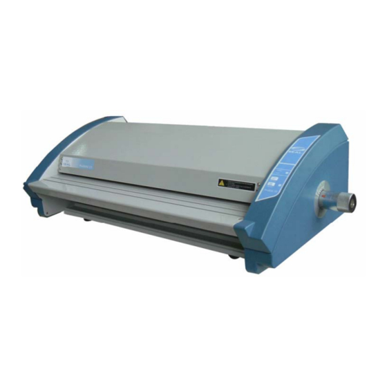
SEAL ProSEAL 44 Service Manual
Hide thumbs
Also See for ProSEAL 44:
- Owner's operation manual (18 pages) ,
- Owner's operation manual (18 pages)

Subscribe to Our Youtube Channel
Related Manuals for SEAL ProSEAL 44


Summary of Contents for SEAL ProSEAL 44
- Page 1 ® ProSEAL 44 Laminators ® Seal Brands…the finishing Service Manual ® ProSEAL 44 Laminators...
-
Page 2: Table Of Contents
Table of Content 1.Safety Precautions ………………………………………………………………………… 3 ~ 3 2.Troubleshooting 4 ~ 9 …………………………………………………………………………… 2.1) Rollers Not Heating …………………………………………………………… 4 ~ 5 2.2) Rollers Over Heating ………………………………………………………… 6 ~ 6 2.3) Rollers Not Running …………………………………………………………… 6 ~ 7 2.4) No Main Power ………………………………………………………………… 8 ~ 9 3.Replacing Parts ………………………………………………………………………………... -
Page 3: Safety Precautions
1. Safety Precautions Failure to comply any of the following safety procedures could result in serious injury. Please read the instructions carefully and keep for future reference. 1. Only a licensed electrician should install wiring and outlet for the laminator. 2. -
Page 4: Troubleshooting
2. Troubleshooting Note: While repairing: Make sure the power plug is unplugged from the power outlet. Open both side covers and rear cover. Be sure to follow the steps below in order. 2.1 Rollers Not Heating CAUSES: 1. Not in heating mode. 2. - Page 5 3. Blown (burnt) wire fuse (T/Fuse). a. Replace the T/Fuse wire located on the left-hand side. ℃ WIRE-T/FUSE(142 4. Defective Bi-Metal. a. Replace the Bi-Metal BIMETAL(155℃) 5. Defective heater. a. Using the multi-meter, test the continuity of the heater. If it fails, replace the heater. Multi-meter b.
-
Page 6: Rollers Over Heating
2.2) Rollers Over Heating CAUSES 1. Defective T/Fuse wire. 2. Defective heater. 3. Defective main PCB. MEASURES 1. Defective T/Fuse wire. a. Replace the T/Fuse wire located on the left-hand side. ℃ WIRE-T/FUSE(142 2. Defective heater. a. Test continuity of the heater. If it fails, replace the heater. b. - Page 7 MEASURES 1. No power to the unit. a. Make sure the power plug is connected to the proper source of outlet (120V, 15Amp, & single phase). 2. Emergency switch is engaged. Switch is engaged 3. Film is jammed on the rollers. a.
-
Page 8: No Main Power
2.4) No Main Power CAUSES 1. No electricity. 2. Blown main fuse. 3. Defective transformer. MEASURES 1. No Electricity. a. Double check to insure that you have electricity from your outlet. b. Check the circuit breaker. c. Double check that source of power is 120V, 15Amp, and single phase. 2. - Page 9 b. Connect the transformer wires to the main PCB. transformer connecter transformer connecter...
-
Page 10: Replacing Parts
3. Replacing Parts Note: While replacing parts: a. Make sure the power plug is unplugged from the power outlet. b. Open both side covers and rear cover. 3.1 Replacing the Right Cover. a. Take out the three cover screws using Phillips screw driver. (Figure 1) Figure 1 b. -
Page 11: Rear Cover
3.3 Replacing Rear Cover a. Take off the left and right covers. b. Take out the four screws from frames,two screws of each side(Figure 4,Figure 5 Figure 5 Figure 4 3.4 Replacing the Main PCB a. Remove the rear cover and label all the wires before unplugging from the Main PCB. b. -
Page 12: Main Fuse
c. Take out the broken heater (Figure 9) Figure 9 Note: a. When inserting the heater into the roller, rotate the heater slightly and push the rod in gently. b. Use an air blower to blow out the broken pieces of heating rod. (Please ensure that no one is standing on the other side.) 3.7 Replacing the Main Fuse a. -
Page 13: Adjustments
4.Adjustments Adjusting roller pressure: Using a screwdriver turn Clockwise to increase pressure and counter clockwise to decrease pressure. (Figure A) Figure A 1.Using Push-Pull Scale,measure 5 spots as shown on Figure C & D: roller should be 4~5 (the red "Label- Indication" point at"closed"... -
Page 14: Parts List
Parts List MODEL : ProSEAL 44 2006年 07月 18日 REF NO. PART NO. DESCRIPTION MATERIAL Q'TY 013LR3043A BASE-FRONT AL6063 026004005A FOOT RUBBER 013LR3044A BASE-REAR AL6063 350LR3029A PCB-MAIN ASS'Y FR-4 34000S009B POWER TRANSFORMER 120V 50/60 HZ 23200X001A SUPPORT-PCB NYLON 66 013LR3045A FRAME-REAR... - Page 15 124LR4005A CAM S45C 120LR3017A SHAFT-CAM S45C 140LR4019A HOLDER S45C 120LR3019A SHAFT-ROTATION S45C 032LR4015A SHEET-INDICATION PC LEXAN T=0.25 SKE05006D2 SET SCREW M5*6 SUS27 RC001200C8 SNAP-RING STW-12 WON IL KPS05012D2 KEY-PLAIN 5*5*12 SUS27 133LR3003A ROLLER-LAMI,UP STPG, ORG 122LRX4028A BUSH-ROLLER LAMI, UP S45C 12200X037A DU-BUSHΦ30X20,FLANGE 133LR3003B ROLLER-LAMI,LO STPG, ORG...
-
Page 16: Exploded Drawings
6. ProSEAL 44 Explode View ProSEAL 44 Explode View Frame L Frame R Frame, Roller and Other View Wire, Front Table and Sensor... - Page 17 ProSEAL 44 Explode...
- Page 18 Frame-L NO. PART NO. NAME DU-BUSH Φ 12X10,FLANGE 18 12200X032A 19 013LR3046A FRAME-L 20 141LR3013A PLATE-PRESSURE,L 21 141LR4060A PLATE-PRESSURE,LAMI 24 138LR4015A SPRING-PRESSURE 25 141LR4064A BRACKET-TABLE 37 124LR4005A 44 KPS05012D2 KEY-PLAIN 46 122LR4028A BUSH-ROLLER LAMI, UP DU-BUSH Φ 30X20,FLANGE 47 12200X037A 56 141LR4019A BRACKET-HEATER UP 57 141LR4027A...
- Page 19 Frame-R NO. PART NO. NAME DU-BUSH Φ 12X10,FLANGE 18 12200X032A 21 141LR4060A PLATE-PRESSURE,LAMI 24 138LR4015A SPRING-PRESSURE 26 013LR2054A FRAME-R 27 141LR3014A PLATE-PRESSURE,R 28 134LR4003A BUSH-PULLEY 29 134LR4001A PULLEY-CHAIN 30 BHE06045D2 HEXA BOLT 31 WPB06012D2 WASHER-PLAIN 32 141LR4063A BRACKET-HANDLE 37 124LR4005A 39 140LR4019A HOLDER 40 120LR3019A...
- Page 20 Frame,Roller and Other View PART NO. NAME 013LR3043A BASE-FRONT 026004005A FOOT 013LR3044A BASE-REAR 350LR3029A PCB-MAIN ASS'Y 34000S009B POWER TRANSFORMER 23200X001A SUPPORT-PCB 013LR3045A FRAME-REAR 36400X002B SWITCH-MAIN 8216 B/R 1/10 SIGNAL-LUX SPA 23300X001A BUSHING-CORD 36600X002A MAIN FUSE-BLOCK 011LR3001B TOP-COVER 011LR4001A BRACKET-COVER1,R 011LR4002A BRACKET-COVER1,L 011LR4003A BRACKET-COVER2...
- Page 21 Wire,Front Table,and Sensor PART NO. NAME 380CR4008A POWER-CORD;AC120V 15A 1.8M 141LR4064A BRACKET-TABLE 021LR3003A CASE-SENSOR,UP 021LR3004A CASE-SENSOR,LO 313LR3001A SENSOR-ASS,Y 014LR3002A TABLE-FRONT 381LR4074A WIRE-HEATER; EU,UL1015 AWG#16, WHT 381LR4061B WIRE-AC IN; UL 1015 AWG#16,WHT/BLK 381LR4075A WIRE-BIMETAL; UL 1015 AWG#14,BLK 381LR4076A WIRE-TEMP FUSE; UL 1015 AWG#14,142℃,15A 381LR4088A WIRE-FUSE;...
-
Page 22: Wire Diagram
<ProSEAL 44 Wire Diagram>... - Page 23 <MAIN PCB LAYOUT> Wire-Sensor Motor Main-PCB Wire-Main Transformer Wire-Heater...
- Page 24 <Frame-L and Frame-R Heater Layout> ℃ Wire-T/Fuse(142 Wire-Heater Bimetal(155℃) Wire-Main Wire-Bimetal...
Need help?
Do you have a question about the ProSEAL 44 and is the answer not in the manual?
Questions and answers