
Related Manuals for SMA Windy Boy WB 1100LV


Summary of Contents for SMA Windy Boy WB 1100LV
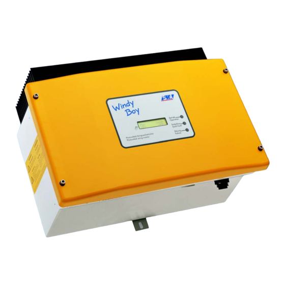
- Page 1 Windy Boy WB 1100LV Inverter for Wind Energy Power Plants User Manual Version 1.0 WB1100LV-11:FE2606 TBE-WB1100LV...
-
Page 3: Table Of Contents
Technologie AG Table of Contents Table of Contents Explanation of Symbols Used ....5 Introduction ......7 Safety Instructions . - Page 4 Table of Contents Technologie AG Sunny Beam ......45 8.2.1 Sunny Data Control Via Sunny Beam ....46 Sunny Boy Control Light .
-
Page 5: Explanation Of Symbols Used
Technologie AG Explanation of Symbols Used 1 Explanation of Symbols Used To ensure optimum use of this document, note the following explanation of the symbols used. This symbol identifies an example. This symbol indicates a notice where failure to follow the advice will make the procedure or operation more difficult. - Page 6 Explanation of Symbols Used Technologie AG Page 6 WB1100LV-11:FE2606 User Manual...
-
Page 7: Introduction
German Professional Association for Precision Engineering and Electrotechnology relating to the "automatic disconnection device for power-generating systems" (SMA grid guard 2) and/or DIN VDE 0126. In addition to this, the Windy Boy complies with the electromagnetic tolerance regulations and the low-voltage regulations of the relevant combined European standards, as confirmed in the CE declaration of conformity (10.3 "Declaration of Conformity (CE)"... - Page 8 PV inverter. Download the Sunny Boy manual from www.SMA.de if you are planning to use the Windy Boy in a photovoltaic system, and contact the SMA Hotline. Page 8 WB1100LV-11:FE2606 User Manual...
-
Page 9: Safety Instructions
There is a danger of burn injury when these parts are touched! The Windy Boy is equipped with the SMA grid guard 2. This is a type of automatic disconnection device. It ensures that the Windy Boy complies with the VDEW (Verband der Elektrizitätswirtschaft –... - Page 10 Safety Instructions Technologie AG Page 10 WB1100LV-11:FE2606 User Manual...
-
Page 11: Unit Description
Technologie AG Unit Description 4 Unit Description 4.1 Appropriate Usage of the Windy Boy The Windy Boy is designed for the conversion of rectified DC voltage from a wind turbine (permanent magnet generator) into alternating current for feeding into the public grid. - Page 12 Unit Description Technologie AG The electronic protection system described here is always preferable to mechanical solutions (pitch control, "turning out of the wind"). Any other use of the Windy Boy voids the warranty. In the event of overvoltage, immediately disconnect the Windy Boy's DC input! The presence of excessive input voltage can lead to irreparable damage! When the Windy Boy receives an excessive DC input voltage, it automatically...
-
Page 13: Structure Of The Device
As long as it is installed and commissioned according to the technical specifications, the Windy Boy can be operated without any further modification or configuration. The device parameters can however be modified, if required. Windy Boy WB 1100LV housing IP65 (outdoor installation possible) SMA grid guard 2 Wind... - Page 14 Unit Description Technologie AG All DC connections and connections for the public grid, as well as any optional communication connections are to be found on the underside of the Windy Boy. The DC side is connected internally via screw terminals. Openings for optional communication via RS232, AC socket for...
-
Page 15: Operating Modes
Technologie AG Unit Description 4.3 Operating Modes The various operating modes are displayed using three light-emitting diodes (LEDs) on the housing cover of the Windy Boy. To allow the device to indicate its operating mode via the integrated LEDs, the Windy Boy must be connected on the DC side. There must be enough wind energy present, so that the Windy Boy has adequate DC voltage. -
Page 16: Critical Faulty Operation
Unit Description Technologie AG 4.3.2 Critical Faulty Operation A comprehensive safety concept has limited the number of critical conditions that can occur to one single situation: Input voltage exceeds the permitted value! This is indicated by the following blink code on the yellow LED: (green) The yellow LED illuminates 4 (red) -
Page 17: Non-Critical Faulty Operation
Technologie AG Unit Description 4.3.3 Non-Critical Faulty Operation All other display codes indicate some form of error condition, which is not usually dangerous to people or equipment, but which should nevertheless be investigated and corrected without delay. Despite all precautions, it is possible that other errors may occur which cannot be displayed (e.g. - Page 18 Unit Description Technologie AG Working Mode The Windy Boy has successfully passed the measurement electronics and SMA grid guard self-tests and has begun feed- The green in operation. LED is The Windy Boy is working normally and is illuminated. feeding...
- Page 19 Technologie AG Unit Description Derating The temperature monitoring of the Windy Boy has reduced the output power to prevent the device from overheating. If this occurs often, this is an indication of The green LED inadequate heat dissipation or excessive goes out briefly input current.
- Page 20 Unit Description Technologie AG Permanent Disable In the event of a recurring fault, the Windy Boy switches to "Permanent Disable" mode, and ceases grid feeding. A fault may exist that cannot be resolved on-site. You can attempt to correct the The yellow error with the aid of a communication LED is...
- Page 21 Technologie AG Unit Description Grid Fault (green) The yellow LED illuminates (red) twice in quick succession. (yellow) LED on LED off The code is repeated 3 times, then begins again. The yellow fault LED illuminates for 5 seconds when the fault occurs, and then begins displaying the blink code of: 3 seconds off, then twice briefly on.
- Page 22 Unit Description Technologie AG Excessive Grid Impedance (green) The yellow LED illuminates 3 (red) times in quick succession. (yellow) LED on LED off The code is repeated 3 times, then begins again. The yellow fault LED illuminates for 5 seconds when the fault occurs, and then begins displaying the blink code of: 3 seconds off, then 3 times briefly on.
- Page 23 Technologie AG Unit Description Excessive Input Voltage (green) The yellow LED illuminates 4 (red) times in quick succession (yellow) LED off LED on The code is repeated 4 times, then begins again. The yellow fault LED illuminates for 5 seconds when the fault occurs, then begins displaying the blink code of: 3 seconds off, then 4 times briefly on.
- Page 24 Unit Description Technologie AG Device Fault (green) The yellow LED illuminates 5 (red) times in quick succession (yellow) LED off LED on The code is repeated 5 times, then begins again. The yellow fault LED illuminates for 5 seconds when the fault occurs, then begins displaying the blink code of: 3 seconds off, then 5 times briefly on.
-
Page 25: Information On The Display
Technologie AG Unit Description 4.4 Information on the Display Since 2006, the Windy Boy has been equipped with an LCD display in the housing cover as standard. Activating the Display Illumination The background illumination is switched on by tapping on the housing cover. Tapping again switches the display to the next message. - Page 26 10.2 "Error Messages" (Page 64) of this document. "Error ROM" indicates that the Windy Boy has Error detected an error in the EEPROM firmware. Contact SMA to have the error corrected. Page 26 WB1100LV-11:FE2606 User Manual...
- Page 27 Technologie AG Unit Description Special Display Message Upon Excessive DC Input Voltage If an excessive DC input voltage is present at the !PV-Overvoltage! Windy Boy, this is indicated by rapid blinking of the background illumination and the message shown DISCONNECT DC here to the right.
- Page 28 Unit Description Technologie AG Page 28 WB1100LV-11:FE2606 User Manual...
-
Page 29: Setting The Display Language
Technologie AG Setting the Display Language 5 Setting the Display Language The display language is set using the switches on the underside of the LCD assembly. As the cover must be removed, ask a qualified electrician to disconnect the DC and AC connections from the Windy Boy, according to the installation manual. - Page 30 Setting the Display Language Technologie AG Page 30 WB1100LV-11:FE2606 User Manual...
-
Page 31: Turbine Operation
Technologie AG Turbine Operation 6 Turbine Operation 6.1 Overview The Windy Boy is a single phase inverter that converts DC current into AC current and feeds the energy generated by a wind turbine system into an existing grid. The Windy Boy is externally identical to the Sunny Boy inverter for photovoltaic systems. The Windy Boy does, however, have a special operating mode for wind turbine systems and water turbines, which makes it possible to adjust the output to the characteristic curves of many different manufacturers' wind turbines ("Turbine"... - Page 32 Turbine Operation Technologie AG The diagram shows the combined even function of a typical Windy Boy power/voltage curve. The feed-in AC power is shown here in relation to the Windy Boy's DC input voltage. The adjustable parameters U Start, U WindStart, U WindMid, P- WindMid, U...
-
Page 33: Characteristic Curve Operation In "Turbine" Mode
Technologie AG Turbine Operation 6.3 Characteristic Curve Operation in "Turbine" Mode Note: The characteristic curve of the Windy Boy only approximates the actual characteristics of a real wind turbine. Consult the manufacturer of your wind turbine for the typical characteristics of your turbine before changing the characteristic curve parameters. - Page 34 Turbine Operation Technologie AG The characteristic curve ends at the maximum permissible DC input voltage of the Windy Boy, which must never be exceeded. Shutdown Procedure If the wind strength is so low that the DC input voltage falls below <Umin> (an internally calculated minimum level for operation), then the Windy Boy operates without feeding power into the grid for the period defined in <T-Stop>.
-
Page 35: General Example Settings
Technologie AG Turbine Operation 6.4 General Example Settings Note that the following example only represents a starting point for operation with a wind turbine. <UpvStart> is set approximately 20 % lower than the lower limit of the Windy • Boy's MPP range: - This results in early activation of the Windy Boy. - Page 36 Turbine Operation Technologie AG This shortens the period waited before activation (please observe the regulations of the local energy supplier). Only change the operating parameters if you know exactly what you are doing! Page 36 WB1100LV-11:FE2606 User Manual...
-
Page 37: Changing The Power Curve With The Sunny Data Pc Software And The Usb Service Interface
You will need to install the Sunny Data software on your PC. This software is available for free from the download area at www.SMA.de. The Sunny Data software is a PC program for direct monitoring and configuration of your Windy Boy, and also allows visualization and logging of system parameters. -
Page 38: Installation Of The Usb Service Interface
Turbine Operation Technologie AG 6.5.1 Installation of the USB Service Interface • Disconnect the Windy Boy from the grid voltage. This is achieved either by pulling the fuse in the domestic power supply, or by pulling out the AC connector of the Windy Boy's grid connection. - Page 39 Technologie AG Turbine Operation • Check whether the Windy Boy's LEDs indicate correct operation. In order to configure the Windy Boy, a DC input voltage - within the MPP range of the Windy Boy - must be present. The Windy Boy must also be connected to the grid voltage.
- Page 40 Turbine Operation Technologie AG Page 40 WB1100LV-11:FE2606 User Manual...
-
Page 41: Maintenance And Care
Technologie AG Maintenance and Care 7 Maintenance and Care To enable the Windy Boy to be used also outdoors in places that are difficult to access, it has been constructed for low maintenance. However, in the interests of maximum yields, the operator should check, weekly if possible, and under various wind conditions, whether the Windy Boy's display indicates plausible normal operation (see section 4.3.4 "Description of the Operating Modes"... - Page 42 Maintenance and Care Technologie AG Page 42 WB1100LV-11:FE2606 User Manual...
-
Page 43: Extensions
With the Windy Boy, the wind turbine system can be monitored in a number of different ways. SMA offers a range of products for this purpose, allowing you to install a tailor- made monitoring system for your system. If you require more details regarding the Windy Boy products, order the Sunny Family catalog, or visit www.SMA.de. -
Page 44: Sunny Data Via Powerline
Extensions Technologie AG 8.1.1 Sunny Data Via Powerline "Wireless" communication via the mains power line. (up to 50 Windy Boys) Requirements: The Windy Boys must be equipped with a Powerline Piggy-Back and the PC must be equipped with an SWR-COM / USB-COM plug modem. The connection to a PC via the SWR-COM or SWR-COM-USB is described in the documentation for the SWR-COM / SWR-COM-USB. -
Page 45: Sunny Data Via Rs485
Technologie AG Extensions 8.1.3 Sunny Data Via RS485 Communication via cable. (up to 50 Windy Boys) Requirements: All Windy Boys must be equipped with an RS485 Piggy-Back, the connection to the PC usually occurs via an RS485/RS232 interface converter connected to the COM1 or COM2 port or via an RS485/USB interface converter connected to the USB port. -
Page 46: Sunny Data Control Via Sunny Beam
Extensions Technologie AG 8.2.1 Sunny Data Control Via Sunny Beam Communication with a PC via Sunny Beam (up to 4 Windy Boys) Requirements: All 4 Windy Boys must be equipped with a Radio Piggy-Back and accessible from the Sunny Beam for system monitoring. The Sunny Beam is connected to the PC via a USB cable. -
Page 47: Sunny Boy Control
Technologie AG Extensions 8.4 Sunny Boy Control The data logger for systems with up to 50 Windy Boys. The connection between the Sunny Boy Control and the Windy Boys can be realized as follows: Powerline - "wireless" communication via the mains power line. Requirements: All the Windy Boys must be equipped with a Powerline Piggy-Back. -
Page 48: Sunny Data Control
Extensions Technologie AG 8.6 Sunny Data Control The PC program for system monitoring and visualization on a PC for systems with a Sunny Boy Control. Requirements: A system with a Sunny Boy Control, Sunny Boy Control Plus or Sunny Boy Control Light with a connection to a PC. Connection also possible Internet via modem... -
Page 49: Sunny Webbox
Powerline Sunny Matrix 8.8 Sunny Portal The Sunny Portal is a high performance interface from SMA for the monitoring and presentation of your system in the Internet. Details can be obtained from the Sunny Family catalog or directly at www.SUNNY-PORTAL.com. - Page 50 Extensions Technologie AG Page 50 WB1100LV-11:FE2606 User Manual...
-
Page 51: Technical Data
Technologie AG Technical Data 9 Technical Data 9.1 Generator Connection Data Description Short Setting descr. Max. input open circuit voltage 60 V DC 0 (based on -10 °C cell temperature) Input voltage, MPP range 21 V ... 60 V Nominal DC operating voltage 25 V DC nom Max. -
Page 52: Grid Connection Data
Germany: 198 ... 253 / 260 V AC Operating range, grid frequency 45.5 ... 54.5 Hz Germany: 47.55 ... 50.2 Hz All-pole isolator automatic disconnection device ("SMA on grid side grid guard 2"), double implementation Power factor (based on the cos phi... -
Page 53: Device Description
Max. efficiency 92 % ηeuro European standard efficiency 90,4 % The efficiency of the Windy Boy WB 1100LV is heavily dependent on the DC input voltage. The lower the input voltage, the higher the efficiency. Output power [W] User Manual WB1100LV-11:FE2606... - Page 54 Technical Data Technologie AG Page 54 WB1100LV-11:FE2606 User Manual...
-
Page 55: General Information
Technologie AG General Information 10 General Information 10.1 Measurement Channels and Messages If your Windy Boy is equipped with a communication component, then numerous measurement channels and messages can be incorporated into diagnostics. These can be useful for improved performance and for error prevention. The following abbreviations apply: BFR: Operation control unit... -
Page 56: Status Messages
General Information Technologie AG 10.1.1 Status Messages The Windy Boy produces a range of status messages, depending on the mode in which it is currently operating. The status messages can vary, depending on the type of communication system you are using. Name Explanation derating... -
Page 57: Windy Boy Operating Parameters
Technologie AG General Information Name Explanation U-Konst / Constant voltage operation (the input voltage is predefined; the Windy Boy operates in neither MPP mode nor Turbine mode). In V-Const some cases, this can be set as the operating mode. Warten / The switch-on conditions are not (yet) satisfied. - Page 58 General Information Technologie AG Name Explanation AntiIsland-Freq Repetition rate of the AntiIsland process (alternative anti- islanding process, which is deactivated for Germany). Betriebsart / Operating mode of the Windy Boy: Operating mode MPP: Maximum power point UKonst: Constant voltage mode (target voltage is defined in "Usoll-Konst") IKonst: Operating mode for test purposes Stop: Disconnection from grid, no operation...
- Page 59 AC side) or in "Stop" mode. Inst.-Code Parameters for stand-alone grid recognition can only be changed after entering the SMA grid guard password. LDVtgC Compensation for the voltage drop in the cabling. With this parameter, the voltage drop between the inverter and the grid connection point is taken into account.
- Page 60 General Information Technologie AG Name Explanation Uac-Tavg Averaging time for measuring grid frequency. UdcWindMax Defines the voltage at the moment when the Windy Boy begins feeding maximum power into the grid. UdcWindMid Defines the voltage threshold, after which the curve climbs more steeply.
-
Page 61: Parameter Settings For Germany
Technologie AG General Information 10.1.4 Parameter Settings for Germany Grayed-out parameters are only displayed in installer mode. The table below contains the parameters that are applicable in Germany. Name Unit Value Range Factory Setting ACVtgRPro 230 ... 300 V AntiIsland-Ampl * grd 0 ... -
Page 62: Country-Specific Parameter Settings
26 ... 63 Parameters designated with * are safety-related grid monitoring parameters. To change the SMA grid guard parameters, you must enter your personal SMA grid guard password (Inst.-Code). Call the Sunny Boy hotline to obtain your personal SMA grid guard password. -
Page 63: Non-Modifiable Parameters
Technologie AG General Information 10.1.6 Non-Modifiable Parameters The following parameters are displayed in the parameter list but cannot be changed: Name Unit Factory Setting Fac-Pderating Fac-Tavg Plimit 1100 SMA-SN Software-BFR Software-SRR Uac-Tavg User Manual WB1100LV-11:FE2606 Page 63... -
Page 64: Error Messages
ACVtgRPro (operating parameter: ACVtgRPro) for voltage quality monitoring. If the grid voltage is continuously within the acceptable range, yet the "ACVtgRPro" error is still displayed, contact the SMA hotline. Bfr-Srr Internal measurement comparison error or hardware defect. - Page 65 Overcurrent on the AC side. This error code is displayed if the current in the AC grid is larger than specified. Check the system configuration and the grid conditions. K1-Schliess / Error during relay test. Contact SMA if this error occurs often or several times in succession. K1-Trenn MSD-Fac Internal measurement comparison error or hardware defect.
- Page 66 Consult a trained electrician to have the fault corrected. You can find instructions on how to change the varistors in the installation manual. The Windy Boy firmware is faulty. Contact SMA if this error occurs frequently. Shutdown Temporary Windy Boy fault Trafo-Temp-F Unacceptably high temperatures have occurred at the transformer.
- Page 67 Technologie AG General Information Error Code Description UpvMax Overvoltage at DC input. Immediately disconnect the DC input of the Windy Boy. Otherwise the Windy Boy could be severely damaged! Check the configuration of your system and measure the DC voltage before reconnecting the Windy Boy to the DC voltage.
-
Page 68: Declaration Of Conformity (Ce)
We declare that the above specified devices are compliant with the regulations of the European Community, in terms of the design and the version fabricated by SMA. This especially applies for the EMC Regulation defined in 89/336/EWG and the low voltage regulation defined in 73/23/EWG. - Page 69 Placa de identificación donde aparece impreso, en lugar de "SB xxxx", "WB(SB) xxxx". Por las razones expuestas anteriormente, todos los certificados referentes a las características del inver- sor "Sunny Boy" son transferibles a los correspondientes inversores "Windy Boy". SMA Technologie AG Hannoversche Straße 1-5 34266 Niestetal Tel.
- Page 70 In virtù ai motivi suddetti, tutte le certificazioni relative agli inverter "Sunny Boy" sono trasferibili sui corr- rispondenti inverter "Windy Boy". Niestetal, 2.1.2006 Sunny Boy Windy Boy SB 700 WB 700 SMA Technologie AG SB 1100 WB 1100 SB 1100LV WB 1100 SB 1700 WB 1700...
-
Page 71: Clean Report Of Findings
General Information 10.4 Clean report of findings The Windy Boy is equipped with the "SMA grid guard 2" automatic disconnection device and is covered by the industrial trade association "SMA grid guard, version 2" clean report of findings. User Manual... - Page 72 General Information Technologie AG Page 72 WB1100LV-11:FE2606 User Manual...
-
Page 73: Stand-Alone Systems
Technologie AG Stand-Alone Systems 11 Stand-Alone Systems The Windy Boy is suitable for use in stand-alone systems based on the Sunny Island. For this purpose, the Windy Boy requires extra settings to ensure optimal operation and to deactivate the standard grid monitoring settings. Refer to the Sunny Island manual for all further relevant information. - Page 74 Stand-Alone Systems Technologie AG Page 74 WB1100LV-11:FE2606 User Manual...
-
Page 75: Contact
• Communication • Serial number of the Windy Boy • Inverter's blink code or display Address: SMA Technologie AG Hannoversche Strasse 1 - 5 34266 Niestetal Germany Tel.:+49 561 95 22 - 499 Fax:+49 561 95 22 - 4699 hotline@SMA.de www.SMA.de... -
Page 76: Exclusion Of Liability
The information contained in this document is the property of SMA Technologie AG. Publishing its content, either partially or in full, requires the written permision of SMA Technologie AG. Any internal company copying of the document for the purposes of evaluating the product or its correct implementation is allowed and does not require permission. - Page 78 Sales Solar Technology www.SMA.de SMA Technologie AG Hannoversche Strasse 1–5 34266 Niestetal, Germany Tel. : +49 561 9522 4000 Fax: +49 561 9522 4040 E-Mail: Info@SMA.de Freecall: +800 SUNNYBOY Freecall: +800 7 8 6 6 9 2 6 9 Innovation in Systems Technology...
Need help?
Do you have a question about the Windy Boy WB 1100LV and is the answer not in the manual?
Questions and answers