Kenmore 721.80032 Installation Insrtuctions
Microwave hood combination
Hide thumbs
Also See for 721.80032:
- Installation instructions manual (21 pages) ,
- Use & care manual (33 pages) ,
- Installation instructions manual (21 pages)
Advertisement
Table of Contents
- 1 Your Safety First
- 2 Parts, Tools, Materials
- 3 Step1: Prepare Theelectrical Connections
- 4 STEP2 : PREPARE Theventing SYSTEM
- 5 Duct Length
- 6 STEP3 : PREPARE Theventing BLOWER
- 7 Electrical Shock Hazard
- 8 Vented Installation
- 9 WALL VENTED Installation
- 10 ROOF VENTED Installation
- 11 Step 6 :Attachtheoven to Thewall
- Download this manual
Models/Modelos
721.80032
721.80033
721.80034
721.80039
721.80042
721.80043
721.80044
721.80049
721.81043
721.85032
721.85033
721.85039
Read and save these
installation
instructions,
Lea y guarde
estas
instrucciones
de
instalaci6n
iNSTALLATiON
iNSTRUCCIONES
iNSTRUCTiONS
!
DE INSTALACION
i
i
Microwave Hood Combination
Combinaci6n M icroondas C ampana
Part No. MFL39433001
Sears, Roebuck and Co., Hoffman Estates,IL 60179
www.sears.com
Advertisement
Table of Contents

Related Manuals for Kenmore 721.80032


Summary of Contents for Kenmore 721.80032
- Page 1 Models/Modelos iNSTRUCCIONES DE INSTALACION 721.80032 721.80033 721.80034 721.80039 721.80042 721.80043 721.80044 721.80049 721.81043 721.85032 721.85033 721.85039 Read and save these Microwave Hood Combination installation instructions, Combinaci6n M icroondas C ampana Lea y guarde estas instrucciones instalaci6n Part No. MFL39433001 Sears, Roebuck and Co., Hoffman Estates,IL 60179...
-
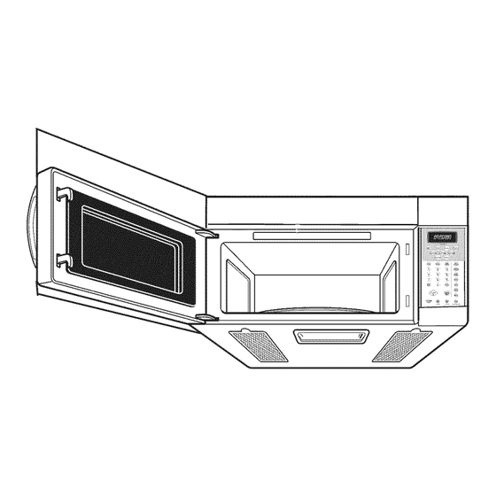
Page 2: Your Safety First
YOUR SAFETY FIRST BEFORE YOU START * Proper installation is the installer's responsibility! - Read the entire manual before you begin. - The model number label is located on the oven front. See Figure 1. - Mounting plate is located on back side of microwave oven. See Figure 2. BE SURE TO READ THE FOLLOWING SAFETY iNSTRUCTiONS: Model... - Page 3 YOUR SAFETY FIRST • THIS APPLIANCE MUST BE GROUNDED! - if there is an electrical short circuit, grounding reduces the risk of electrical shock by providing escape wire for the electric current. This appliance is equipped with a cord having a grounding wire with a grounding plug.
- Page 4 YOUR SAFETY FIRST • MAKE SURE YOU HAVE ENOUGH SPACE AND SUPPORT. - Mount the oven against a flat, vertical wail, so that it is supported by the wail. The wall should be constructed of minimum 2" x 4" wood studding and 3/8"...
-
Page 5: Parts, Tools, Materials
PARTS, TOOLS, MATERIALS THE FOLLOWING PARTS ARE SUPPLIED WiTH THE OVEN: NOTE: Depending on your ventilation requirements, you may not use all of these parts. Damper/duct connector One power cord clamp (for roof vented or wall vented installation). One dark-colored mounting screw (to hold the power cord). - Page 6 PART TOOL MATERIALS YOU WILL NEED THE FOLLOWING TOOLS AND MATERIALS FOR THEINSTALLATION: Carton or other heavy material for covering the counter top. Clear tape Stud finder or thin nail. (for taping the templates to the wail). Saber Key hole saw (for the power cord hole). (for cutting vent holes for roof or wail venting).
-
Page 7: Step1: Prepare Theelectrical Connections
STEP1: PREPARE THEELECTRICAL CONNECTIONS WARNING AVOID ELECTRICAL SHOCK[ THIS APPLIANCE MUST BE GROUNDED[ 1. Locate the grounded electric outlet for this oven in the cabinet above the oven, as shown in Figure 4 Detail. NOTE: The outlet should be on a circuit dedicated to the Upper Cabinet .. -
Page 8: Step2 : Prepare Theventing System
STEP2 : PREPARE THEVENtiNG SYSTEM NOTE: The ductwork you need for outside ventilation is not included with your oven. The standard ductwork fittings and length are shown in Figure 9, page 9. WARNING-FIRE HAZARD THIS OVEN MUST BE PROPERLY VENTED! You may vent your oven in one of three ways: Roof Venting: If your oven is located on an outside wall near the roof, as in Figure 6 (3-1/4"... -
Page 9: Duct Length
STEP2 : PREPARE THE VENTING SYSTEM STANDARD FiTTiNGS NOTE: If the existing duct is round, you must use a rectangular-to-round adapter, with a rectangular 3" extension duct installed between the damper assembly the adapter to prevent the exhaust damper sticking. DUCT LENGTH The total length... -
Page 10: Step3 : Prepare Theventing Blower
STEP3 : PREPARE THEVENtiNG BLOWER Your microwave oven is shipped with the blower assembled for room venting (recirculafing). You need to adjust the blower if you want wail vented or roof vented installation. WARNING ELECTRICAL SHOCK HAZARD! UNPLUG UNiT BEFORE WORKING ON iT+ DO NOT PULL OR STRETCH THE BLOWER WtRtNG! Pulling and stretching... -
Page 11: Wall Vented Installation
STEP3 : PREPARE THEVENtiNG BLOWER WALL VENTED iNSTALLATiON 1. Remove one blower unit mounting screw and two BaCk plate blower plate screws. Remove the blower plate from cabinet. See Figure 12. Blower plate 2. Carefully lift the blower unit out of the microwave oven. -
Page 12: Roof Vented Installation
STEP3 : PREPARE THEVENtiNG BLOWER ROOF VENTED iNSTALLATiON 1. Remove one blower unit mounting screw and two blower plate screws. Remove the blower plate Blower plate from cabinet. See Figure 18. 2. Carefully lift the blower unit out of the microwave oven. - Page 13 STEP 4: PREPARE THE WALL A ND UPPER CABINET FOR/NSTALLATiO MEASURE AND TACK / TAPE UP THETEMPLATE 1. Using o plumb line and (metal) measuring tope, find. and mark the vertical center line(_)on back wail, as in Figure 22. 2. Find and mark one or two points where the studs ore on the wall (Studs ore normally 16 inches apart).
- Page 14 STEP 4: PREPARE THE WALL AND UPPER CABINET FOR INSTALLATION DRILL THE HOLES iN THE WALL AND UPPER CABINET. WARNING BE VERY CAREFUL WHEN DRiLLiNG HOLES iNTO THE WALL. Electrical wires could be concealed behind the wall covering and if the drill hits electric them could...
- Page 15 STEP 5 • INSTALL THE MOUNTING PLATE TO THEWALL THE OVEN MUST BE CONNECTED AT LEAST ONE WALL STUD 3/1 6" Hole on Studs 3/4" Hole on Dry wall Only 1. Draw a vertical line on the wall at the center of 66"...
- Page 16 STEP 5" INSTALL THE MOUNTING PLATE TO THEWALL TO PREPARE THE REAR WALL CUTOUT OPENING AND EXHAUST ADAPTOR// MOUNTING PLATE FOR WALL VENTING AND ROOF VENTING: NOTE: if room vented installation is used, skip this step. 1. Using the Wail-template. This template wiii give the location...
-
Page 17: Step 6 :Attachtheoven To Thewall
STEP 6 :ATTACHTHEOVEN TO THEWALL WARNING Power cord You will need two people to lift this microwave. Failure to use more than one person could result in personal injury. cord hoie 1. Carefully lift microwave oven and hang it on support tabs (See Figure 26) at the bottom of the mounting... - Page 18 STEP 6 :ATTACHTHEOVEN TO THEWALL 5. Roof vented installation: See Figure 32. Install ductwork through the vent opening in the upper cabinet. Complete the venting system through the roof according to the method needed. See _°PREPARE THE VENTING SYSTEM," STEP 2 on the page 8.
- Page 19 Printed in china...
Need help?
Do you have a question about the 721.80032 and is the answer not in the manual?
Questions and answers