Table of Contents
Advertisement
Thank you for purchasing our embedded Net DVR. This manual is applicable for
DS-7000HI series Net DVR. Please read this User Manual carefully to ensure that you
can use the device correctly and safely.
The contents of this Manual are subject to change without notice.
DS-7000HI Series Net DVR
User Manual
V2.1S
1
Advertisement
Table of Contents

Subscribe to Our Youtube Channel
Related Manuals for HIKVISION DS-7000HI Series


Summary of Contents for HIKVISION DS-7000HI Series
-
Page 1: User Manual
V2.1S Thank you for purchasing our embedded Net DVR. This manual is applicable for DS-7000HI series Net DVR. Please read this User Manual carefully to ensure that you can use the device correctly and safely. The contents of this Manual are subject to change without notice. -
Page 2: Table Of Contents
Index Safety Precaution......................5 Chapter1 Product Introduction..................8 Summary ........................8 Model Description......................8 Features .........................9 Typical Application .....................11 Chapter2 Installation ....................12 Check DVR and It’s Accessories ................12 HDD Installation ......................12 DVR Rear Panel Connection ..................17 External Alarm In/Out Connection ................18 Powering up ........................19 Chapter3 Operational Instructions................ - Page 3 5.5.1 Camera Name Setup ...................65 5.5.2 Video Parameters Setup ................66 Mask Area Setup ......................68 View Tampering Alarm ....................71 Video Loss Alarm......................73 Motion Detection Alarm .....................75 5.10 Live View Setup......................79 5.11 Recording Setup ......................82 5.12 Alarm I/O Setup ......................87 5.13 Network Setup......................92 5.13.1 Network Basic Settings................92 5.13.2...
- Page 4 UTP Network Connecting.....................126 RS232 Connecting ......................128 Appendix C Specifications................... 129 Appendix D Quick Search ................... 131 Appendix E Troubleshooting ..................133 Appendix F Product Service ..................135 Appendix G Customer Information Card ..............136...
-
Page 5: Safety Precaution
Safety Precaution Caution: To reduce the risk of electric shock, do not remove cover, (unless you wish to install hard disks, please see the section "Hard Disk Installation"). No User-serviceable parts inside. Refer servicing to qualified service personnel. Important Safeguards: 1. - Page 6 13. Unplug this unit during lightning storms or when unused for long periods of time. 14. Refer all servicing to qualified service personnel. Servicing is required when the apparatus has been damaged in any way, such as power-supply cord or plug is damaged, liquid has been spilled or objects have fallen into the apparatus, the apparatus has been exposed to rain or moisture, does not operate normally, or has been dropped.
- Page 7 22. Danger of explosion if battery is incorrectly replaced. Replace only with the same or equivalent type. Dispose of the replaced battery in an environmentally friendly way. Cleaning You can clean the unit with a moist fluff-free cloth or shammy leather cloth. Warning This device is intended for use in public areas only.
-
Page 8: Chapter1 Product Introduction
TCP/IP. The firmware is burned in the flash, more stable and reliable. DS-7000HI series device has both the features of digital video recorder (DVR) and digital video server (DVS). It can work stand alone, also be used to build a powerful surveillance network, widely used in bank, telecommunication, transportation, factories, warehouse, irrigation, etc. -
Page 9: Features
Features Compression Support max. 16 channels video input (PAL/NTSC) at most. Each channel is Each camera can support independent, H.264 hardware compression. resolution real time or 2CIF resolution not real time (8FPS per channel). Support both variable bitrate and variable frame rate. Support 4 channels audio inputs. - Page 10 Alarms Support exception alarm, motion detection alarm, external alarm, etc. Others Support IR control. Support multi-level user management. Network Support TCP, UDP, RTP, Multicast for network preview. Support PPPoE for board band dialup. Support PSTN for narrow band dialup. Support remote parameters setup. Alarm information can be sent to remote center.
-
Page 11: Typical Application
1.4 Typical Application... -
Page 12: Chapter2 Installation
Chapter2 Installation Check DVR and It’s Accessories When you get the product, check that all the items are included in your product package. There is a list in the package. If any of the items is missing, please contact your dealer. - Page 13 3. Open the metal top cover by removing the screws on the side and back of the cover. 4. Install the HDD.
- Page 14 5. Connect HDD and main board with HDD cable. Then connect HDD’s power cable.
- Page 15 6. Check all connections, and mount back the metal cover of the DVR. 7. Switch on the DVR. 8. Press [MENU] key to enter into DVR main menu. Go to the "Utilities" menu and choose "Hard disk" to format the hard disks, Check if all installed disks are detected by the...
- Page 16 DVR, and if the capacity is OK. Choose "Format" and select "All" to format all hard disks. When all disks are formatted a confirmation message will be shown on the screen. Check if all installed disks have the status "OK". The installation of HDD is complete.
-
Page 17: Dvr Rear Panel Connection
DVR Rear Panel Connection Notice: Please refer to real product for different model. DS-7016HI Rear Panel DS-7004HI Rear Panel Index Physical Interface Description Standard BNC. Video Input Connect monitor, output video and menu. Video Output Ω Audio Output 1 channel RCA (1.0 Vp-p, 75 Ω... -
Page 18: External Alarm In/Out Connection
External Alarm In/Out Connection Alarm input dry node Alarm input port (dry node): G (GND): Connect the GND of sensor. 1~8: Alarm input, support normal open/normal close. 0: Reserved. Alarm output: 1G~4G: 4 relay output. Alarm output connection Connect with DC device Connect with AC device... -
Page 19: Powering Up
2.5 Powering up 1. Switch on all connected equipment. 2. Connect the power cable to the unit 3. Switch on the power... -
Page 20: Chapter3 Operational Instructions
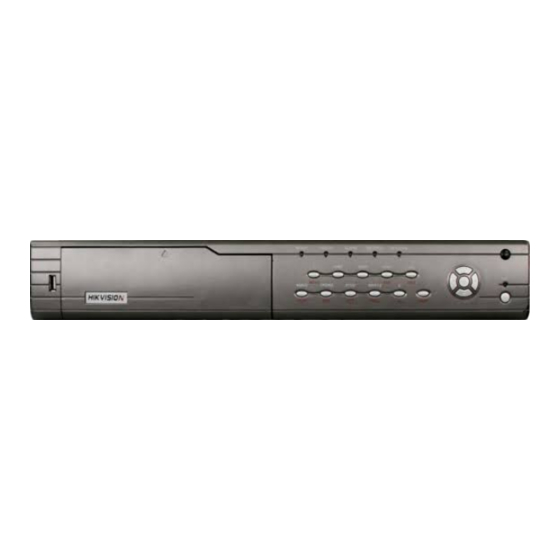
Chapter3 Operational Instructions DVR Front Panel Index Type Name Description State READY DVR is ready Lamps STATUS Green means you can use IR remote control ALARM Red means there is alarm RECORD Twinkle in red means reading or writing HDD NETWORK Network status Lamp IR receiver... - Page 21 Input switch (number, lower case, upper case and symbol) [FOCUS+] in PTZ control In preview mode, display or hide the channel status bar SHIFT Switch between numeric keys and function keys Control Direction Composed of [ ] , [ ], [ ] and [ ] Keys Keys 1.
-
Page 22: Ir Control
IR Control Index Name Description POWER Turn off device Enable/Disable IR remote control Numeric Keys Same as numeric keys of front panel EDIT Same as [EDIT] key of front panel Same as [A] key of front panel Same as [REC] key of front panel PLAY Same as [PLAY] key of front panel INFO... - Page 23 Same as [ESC] key of front panel Reserved Reserved for future usage Same as [F1] key of front panel Lens control IRIS, FOCUS ZOOM for lens control Same as [F2] key of front panel Loading the batteries into the IR controller 1.
-
Page 24: Osd Menu Description
OSD Menu Description 3.3.1 Main Menu Items Menu Name Function Menu Name Function Device ID Camera name and position Require Password Color Video standard OSD Display mode, position Brightness and OSD style setup Menu transparency Mask area setup Screen saver Display Camera View... -
Page 25: Menu Operation
3.3.2 Menu Operation How to enter into menu mode Press [MENU] key to enter into DVR main menu Press [PLAY] key to enter into playback menu Press [REC] key to enter into manual record menu Press [PTZ] key to enter into PTZ control interface Notes: You must input user name and password. - Page 26 Each menu contains different kinds of items. There is a small rectangular frame named “Active Frame” which is pointing to the selected item. This “Active Frame” can be moved by direction keys ([↑] [↓] [ ] [ ]). There are such kinds of menu items: Check Box: Provide 2 options, “...
- Page 27 How to exit menu Press [PREV] or [ESC] key to exit menu and return to preview mode.
-
Page 28: Character Input
Character Input In the menu interface, if you enter into edit status, for example, in the “camera name” edit box at the bottom of screen, the input status is appeared: Here it means you can press numeric keys to input digital number. Press [A] key to change input methods. -
Page 29: Chapter4 Basic Operation Guide
Chapter4 Basic Operation Guide Power on Note: Please make sure the power supply matches DVR and AC cable connected correctly. Before switch DVR on, please connect one monitor with VOUT or VGA interface. Otherwise, you can not see graphic user interface and can not operate. -
Page 30: Live View
Live View DVR will enter into live view mode after it is started. On preview screen, you can see date, time, camera’s name and camera status icon. Set system date and time in “Display” menu, referring to 5.4; Change camera name in “Camera”... - Page 31 Green Continuous recording Blue Motion detect recording External alarm recording Camera alarm status is following: Icon Icon Color Status Description White Video signal lost Yellow View tampering alarm Pink Motion & External alarm Green No alarm Blue Motion alarm External alarm Press numeric keys to switch over individual camera live view.
- Page 32 [2] key to preview 2 camera. If DVR has 10 or more than 10 channels, press two numeric keys to switch to corresponding channel. For example, press [0] [2] to preview camera; and press [1] [2] keys to preview 12 camera.
-
Page 33: Login
Login Note: When DVR is delivered from factory, there is only one default administrator named “admin”, and password is “12345”. The administrator’s name can not be modified, while the password can be modified. The administrator can create 15 users and define their user rights. Login dialog is following: Use [ ] / [ ] keys to select one user, press [ ] key to enter into “Password”... -
Page 34: Ptz Control
PTZ Control Note: The user must have the “PTZ control” right. Please refer to “PTZ Setup” in chapter 5.14. PTZ control interface In preview mode, press [PTZ] key, in the login dialog, select one user name and input the correct password, you can enter into PTZ control interface. In menu mode, press [PTZ] key, you can enter into PTZ control interface directly. - Page 35 After you select the camera PTZ, you can use the short keys to control PTZ. PTZ control keys description Direction control keys: [↑], [↓], [←], [→] ZOOM control keys: [ZOOM+], [ZOOM-] FOCUS control keys: [FOCUS+], [FOCUS-] IRIS control keys: [IRIS+], [IRIS-] Adjust preset keys: [REC/SHOT];...
-
Page 36: Manual Record
Manual Record Note: The user must have the corresponding right, DVR has HDD and HDD is formatted already. Manual record In live view mode, press [REC] key, in the pop-up login dialog, select the name and input the correct password, you can enter into the “Manual Record” interface. In menu mode, press [REC] key to enter into “Manual Record”... - Page 37 Start All: Press this button to start all channels recording. Stop All: Press this button to stop all channel recording. Exit manual record Press [ESC] key to enter into preview mode. Press [MENU] key to enter into main menu. Press [PLAY] key to enter into playback menu. Press [PTZ] key to enter into PTZ control mode.
-
Page 38: Playback
Playback Note: The user must have “Playback” right. Playback interface In live view mode, press [PLAY] key, in the pop-up login dialog, select username and input correct password, you can enter into “Playback” interface. In menu mode, press [PLAY] key, you can enter into “Playback” interface directly. Description If DVR only supports one channel playback, you can not select second channel. - Page 39 Time Section: You can define the search time section. Move “Active Frame” to the time edit box, use numeric keys to input the detail time. Search: Search the matched recorded files and display them in the list box. If there is not matched file, a corresponding dialog box will be pop-up.
- Page 40 If the matched files are more than 8, you can use “Page No.” to select page (use numeric keys or [↑] [↓] keys to select page). In the file list box, use [↑] [↓] keys to move the scroll bar to the file, press [ENTER] key to playback the file. If the second channel is selected, these two channels can be playback synchronously.
- Page 41 Frame by Frame) Pause/Continue: Press [ENTER] to pause/continue playback. If played frame by frame, Press [ENTER] to play one frame. Copy segment: [EDIT] Exit: [ESC] Playback switch: When in 2-ch playback, press [PREV] to switch between main channel and second channel. Note: When DVR is busy, if you select high play speed, maybe there is difference for actual play speed.
-
Page 42: Backup Recorded Files
Backup Recorded Files Note: The user must have “Playback” right. Please connect with backup devices before you start to backup. In the playback interface, you can backup the recorded files. In the preview mode, press [PLAY] key, in the login dialog, select username and input the correct password, you can enter into the playback interface. - Page 43 SATA CD/DVD or SATA HDD, and select the corresponding backup device. Step 4: Start and finish backup Move “Active Frame” to “Copy” button and press [ENTER] key to start backup. When backup is started, corresponding message box will pop-up to indicate the result.
- Page 44 Backup File Backup video clips You also can backup the video clips when the file is being playback. The steps are: Enter into the interface of playback the files or playback by time; Press [EDIT] key to start selecting the current playback image, and press [EDIT] again to stop selecting.
- Page 45 you press “Cancel” button, DVR will abort backup. Backup Video Clips Note: The backup function is effective when two channels are playback synchronously. In such case, each channel can backup 30 segments so 60 segments can be backup for two channels. Playback backup video files You can use our file player software to playback the video files in PC.
-
Page 46: Turn Off Dvr
Turn off DVR Note: Do not switch off the power directly in case of damaging HDD. The correct step is using “Power Off” in the “Utilities” menu, or [POWER] key on the front panel or on IR controller. Shut down DVR normally Use menu Enter into “Utilities”... - Page 47 Shut down DVR abnormally Use the power switch of real panel When DVR is run, if you switch off the power, the HDD in DVR will be damaged. Please avoid such operation. Take away the power cable Please avoid taking away the power cable directly. Note: In some cases, when the power supply is abnormal, DVR will be damaged.
-
Page 48: Chapter5 Advanced Operation Guide
Chapter5 Advanced Operation Guide Only the users that have “Parameters Setup” right need to read this chapter. When the following parameters are modified and saved, you must reboot the DVR to make the new parameters take into effective. Other parameters do not need to reboot. Any network parameters in “Network”... -
Page 49: User Management
User Management When DVR is left from factory, there is one default administrator. The name is “admin” and password is “12345”. The name can not be changed, while the password can be. Move “Active Frame” to “User” item, press [ENTER] key to enter into “User Management”... -
Page 50: Add User
5.1.1 Add User The steps are following: Step 1: Enter into “User Management” menu Step 2: Add new user name In the “User Management” menu, move “Active Frame” to “Add” button and press [ENTER], in the pop-up dialog, input the new user name, press [ENTER] and return “User Management”... - Page 51 Step 3: Setup the password for new user After you add one new user, the password is null. You can skip this step if you do not want to change the password.
-
Page 52: Delete User
5.1.2 Delete User In “User Management” interface, you can use [ ] [ ] keys to select one user, then use [ ], move “Active Frame” to “Del” button, press [ENTER], in the pop-up confirmation dialog, press “Confirm” button to delete the selected user and return. Press “Cancel” or [ESC] to abort deleting. -
Page 53: Password Modification
5.1.3 Password Modification Press [MENU] key, in the login dialog, select the username as “admin”, use [→] key, move cursor to password edit box, input “12345”, press “Confirm” to enter into administrator menu. Move “Active Frame” to “User” icon, press [ENTER] key to enter into “User Management”... - Page 54 In this case, press [ENTER] to return password edit box, and input new password again.
-
Page 55: User Rights
5.1.4 User Rights The new added user has not any operational rights. You must setup rights for him. In the users list box of “User Management” menu, use [ ] [ ] keys to select the new user name, then use [ ] key to “Set Privileges” button, press [ENTER], the user will have the default rights. - Page 56 rights will be aborted. User rights description “Local Rights”: Local rights are for local operation, such as the operation using front panel, IR controller and RS-485 keyboard. PTZ control: Locally control PTZ; Record: Manual start/stop recording; Playback: Local playback and backup the recorded files; Parameters Setup: Locally setup the DVR parameters;...
- Page 57 This MAC address is not the address of DVR but the PC that will access DVR. If you setup this MAC address, only the PC with this MAC address can access this DVR. At PC end, in DOS prompt, you can use “ipconfig” command to get the PC MAC address (6 bytes).
-
Page 58: Device Id
Device ID When you use IR controller to operate DVR, you must use device ID to select DVR. The default device ID of DVR is “88”. If there are more than one DVR in one place, please define different device ID for each DVR. Otherwise, the IR controller will control all DVR with the same device ID at the same time. -
Page 59: Video Standard And Vga Setup
Video Standard and VGA Setup Video standard You can modify video standard to match video input. In “Display” menu: There is a list box named “Video Standard”, you can use [ ] [ ] key to select PAL or NTSC video standard. VGA setup There is one VGA interface at the real panel of DVR. -
Page 61: Day And Time Setup
Day and Time Setup 5.4.1 Day and Time Setting In “Display” menu, you can setup DVR system date and time. -
Page 62: Day And Time Display Mode
5.4.2 Day and Time Display Mode You can setup display properties for each camera, including display status, position and format. Of course, you can copy the properties of one camera to all cameras. In “Image Setup” menu as following, select one camera: Display mode: There... - Page 63 Press [EDIT] key to select OSD format. There are following OSD formats: MM DD YYYY hh:mm:ss (default) MM DD YYYY hh:mm:ss YYYY MM DD hh:mm:ss YYYY MM DD hh:mm:ss Here YYYY means year, MM means month, DD means day, W means weekday, hh means hour, mm means minute and ss means second.
-
Page 64: Daylight Saving Time Setup
5.5.3 Daylight Saving Time Setup In “Display” interface, you can press DST “Setup” button to enter into DST setup interface. DST means Daylight Saving Time, select the check box to enable the function, and you can set DST start time and end time. -
Page 65: Camera Setup
Camera Setup 5.5.1 Camera Name Setup Camera Name In “Image Setup” menu, you can define name for each camera. Please notice that camera’s name can not be copied. The steps of camera name setup: Step 1: Select one camera. Step 2: Move “Active Frame” to camera name edit box, press [EDIT] key to enter into edit status, you can input digital number, uppercase and lowercase characters (refer to Chapter 3.4). -
Page 66: Video Parameters Setup
are: Step 1: Enter into “Image Setup” menu. Step 2: Select one camera. Step 3: Enable the check box on the right side of camera name, then you move “Active Frame” to “Position” button, press [ENTER] to enter into camera name position setup interface, in that interface, you can use [ ] [ ] [ ] [ ] keys to move camera name position. - Page 67 Move “Active Frame” to the “Adjust” button on the right side of Brightness, Contrast, Saturation and Hue, press [ENTER] key, you will enter into the corresponding adjust interface. In the adjust interface, there is one scroll bar at the bottom, you can use [ ] [ ] keys to adjust and can find the video image will be changed at the same time.
-
Page 68: Mask Area Setup
Mask Area Setup In some cases, maybe you want mask the sensitive area. This area will not be preview and recorded. The mask area setup steps are following: Step 1: Enter into “Image Setup” menu: Step 2: Select one camera: You can use [ ] [ ] keys to select one camera. Step 3: Click “Advanced settings”... - Page 69 Step 5: Setup mask area: In the mask area setup interface, there is one small yellow pane on the upper left side. For PAL camera, the whole screen is divided into 22*18 panes (22*15 for NTSC), you can use [ ] [ ] [ ] [ ] keys to move the yellow pane to your hope position and press [EDIT] key, the yellow pane will be turned into red, then you can use [ ] [ ] [ ] [ ] keys to extend the red pane.
-
Page 71: View Tampering Alarm
View Tampering Alarm If you enable this function, when someone blocks the camera spitefully, DVR will make warning alarm. Step 1: Enter into “Image Setup” menu: Step 2: Select camera: Please use [ ] [ ] keys to select one camera. Step 3: Enter into “Advanced settings”... - Page 72 Step 6: Alarm schedule setup: When there is view tampering alarm happened, DVR will handle the alarm based on the schedule. You can set 4 periods for each day one week. Also you can copy the schedule of one day to other days. Notes: Time periods can not overlap.
-
Page 73: Video Loss Alarm
Video Loss Alarm When the video cable or camera has something wrong, the video image is lost. If you enable video loss alarm, in such case, DVR will make alarm. Step 1: Enter into “Image Setup” menu: Step 2: Select camera: Use [ ] [ ] keys to select one camera. Step 3: Enter into “Advanced settings”, enable “Signal Loss”... - Page 74 Step 5: Setup alarm schedule: You can setup working schedule. Only when the video loss is happened in the schedule, DVR will response. Note: The 4 time periods can not overlap. Please reboot DVR to make parameters into effective. Step 6: Setup alarm policy: You can select one or more response solutions, including “On Screen Warning”, “Audible Warning”, “Upload to Center”...
-
Page 75: Motion Detection Alarm
Motion Detection Alarm If you enable this function, when there is motion detected, DVR will make alarm. Step 1: Enter into “Image Setup” menu: Step 2: Select camera: Use [ ] [ ] key to select one camera. Step 3: Select motion detection sensitivity: On the right side of “Motion Det. Level” item, there is a list box. - Page 76 The whole screen is divided into 22*18 panes (NTSC: 22*15). There is one yellow panel on the upper left side. The motion area setup steps are the same as that of mask area setup (refer to chapter 5.6). The only differences are that you can use [PTZ] key to set the whole screen as motion area, and multi motion areas can be defined.
- Page 77 [↓]: Down enlarge red pane; [↑]: Up shrink red pane; [PTZ]: Set whole screen as motion area; [A]: Clear all motion areas; [ENTER]: Save and return “Image Setup” menu; [ESC]: Cancel setup and return “Image Setup” menu; Step 5: Motion alarm policy: Move “Active Frame” to the corresponding “Policy” button of motion detection alarm, press [ENTER] key to enter into “Motion Alarm Handle”...
- Page 78 week. Note: Time periods in one day can not overlap. Step 8: Motion alarm handle method setup: You can select one or more handle methods such as “On Screen Warning”, “Audible Warning”, “Upload to Center” and “Trigger Alarm Output”. Description: If “On Screen Warning” is enabled, when there is motion alarm happened and DVR is in preview mode, DVR will pop-up the related camera.
-
Page 79: Live View Setup
5.10 Live View Setup In “Display” menu, you can setup live view properties. In “Preview” menu, you can setup preview mode, screen switch time, enable or disable audio preview and preview layout. Preview mode: For preview mode item, you can use [↑] [↓] key to select one mode. If DVR has only 1 channel, you can select only “1 Screen”... - Page 80 channels, there are “1 Screen”, “4 Screen”, “9 Screen” “12 Screen” and “16 Screen” options. Switch time: That is image preview switch time. You can use [↑] [↓] keys to select switch time. There are many options, including “5 Seconds”, “10 Seconds”, “20 Seconds”, “30 Seconds”, “1 Minutes”, “2 Minutes”, “5 Minutes”...
- Page 81 After you define the camera preview order, you can select preview mode to meet your demand. Save setup: Press “Confirm” button to confirm preview configuration and return “Display” menu, press “Confirm” button to save changed parameters. Press “Cancel” or [ESC] key to abort. You can press [PREV] button to enter into live preview and change preview screen mode.
-
Page 82: Recording Setup
5.11 Recording Setup In main menu, there is an icon named “Recording”. You can enter into recording menu as following: Recording menu description: If HD Full: There are two options: “Overwrite” and “Stop recording”. If you select “Overwrite” option, when all HDDs in DVR are full, DVR will overwrite the earliest recorded files and continue recording. - Page 83 The bit rate value has following options (bps): 32K, 48K, 64K, 80K, 96K, 128K, 160K, 192K, 224K, 256K, 320K, 384K, 448K, 512K, 640K, 768K, 896K, 1M, 1.25M, 1.5M, 1.75M, 2M and “User define”. The max bit rate selection has relations with resolution. If you select high resolution, you must select high bit rate.
- Page 84 All day recording setup: Step 1: Enter into recording schedule menu In recording menu, use [ENTER] or [EDIT] key to enable record function (“ ” flag), press “Schedule” button to enter into recording schedule menu. Step 2: Select one day and enable all day recording option For “Day”...
- Page 85 Step 1: Enter into recording schedule menu In recording menu, use [ENTER] or [EDIT] key to enable record function (“ ” flag), press “Schedule” button to enter into recording schedule menu. Step 2: Select one day and disable all day recording option For “Day”...
- Page 86 parameters and return main menu. Note: If record type is “Motion Detect” or other related types, you must setup “Motion Detection” in order to trigger motion recording (refer to chapter 5.9). If record type is “Alarm” or other related types, you must setup “Alarms” in order to trigger alarm recording (refer to chapter 5.12).
-
Page 87: Alarm I/O Setup
5.12 Alarm I/O Setup For 4-channel DVR there are 4 external alarm input and 2 relay output. For 8-channel DVR, there are 8 external alarm input and 4 relay output. For 16-channel DVR, there are 16 external alarm input and 4 relay output. In “Alarms” menu, you can setup each external alarm input. - Page 88 Step 4: Alarm trigger record channel setup You can select channels to record for each alarm input. In the sub menu, you can use [ENTER] or [EDIT] key to enable record channel. “×” means disable and “ means enable. Note: In order to trigger the channel to record, in “Recording” menu, you must enable recording and select record type as “Alarm”...
- Page 89 In “Alarm in Handling” sub menu, press “Confirm” button and return “Alarms” menu. In “Alarms” menu, press “Confirm” button to save the parameters. Step 8: PTZ Linkage Move “Active Frame” to “PTZ Linkage” button, press [ENTER] key to enter into “PTZ Linkage”...
- Page 90 Step 9: Copy the parameters to other external alarm input You can copy the parameters of current alarm input to other external input. Step 10: Save setup In “Alarms” menu, press “Confirm” button to save the parameters. Press “Cancel” button or [ESC] key to abort. Alarm relay output setup Step 1: In “Alarms”...
- Page 91 Step 5: Copy one alarm output parameters to other alarm output In “Alarms” menu, you can copy parameters of current alarm output to other alarm output. Step 6: Save setup When you finish setup, in “Alarms” menu, press “Confirm” button to save all parameters.
-
Page 92: Network Setup
5.13 Network Setup If you want to get access to DVR via network, you must setup network parameters. Note: If any network parameter is modified, you must save and reboot DVR to make it into effective. In main menu, move “Active Frame” to “Network” icon and press [ENTER], you can enter into “Network”... -
Page 93: Network Advanced Settings
5.13.2 Network Advanced Settings NIC type: Default is “10M/100M Auto”, the other options are: 10M Half-Dup, 10M Full-Dup, 100M Half-Dup and 100M Full-Dup. IP Server: If DVR uses PPPoE function, and get one dynamic IP address. If you set IP server with one fixed Internet IP, DVR will send some information such as DVR name, DVR serial number, DVR current IP to that fixed IP address. -
Page 94: Dhcp Function
5.13.3 DHCP Function In DVR “Network” menu, if you set the IP as “0.0.0.0”, save and reboot DVR, in reboot process, DVR will search the DHCP server and get one dynamic IP address. This item will display the dynamic IP address. 5.13.4 PPPoE Function Enter into DVR “Network”... -
Page 95: Ip Server Solution For Dhcp
5.13.5 IP Server Solution for DHCP If DVR uses PPPoE function, and get one dynamic Internet IP address. If you set IP server with one fixed Internet IP in DVR Network advanced settings, DVR will send some information such as DVR name, DVR serial number, DVR current IP to that fixed IP address. -
Page 96: Ptz Setup
5.14 PTZ Setup There is one RS-485 port at DVR rear panel used for PTZ control. 5.14.1 PTZ Connection Connect DVR/DVS RS-485 port Pin “T+” with PTZ Pin “A”. Connect DVR/DVS RS-485 port Pin “T-“ with PTZ Pin “B”. If DVR/DVS RS-485 port is RJ45 interface, please refer to DVR/DVS user manual about RS-485 pin definition. - Page 97 PTZ menu description Select channel: Select one PTZ camera. RS-485 parameters: Including baud rate, data bit, stop bit, parity, flow control, etc. These parameters must be the same as those of PTZ protocol. PTZ address: Each PTZ has one different address. PTZ type: DVR had the following PTZ protocol: YouLi, LinLin-1016, LinLin-820, Pelco-p, DM DynaColor, HD600, JC-4116, Pelco-d WX, Pelco-D, VCOM VC-2000, NetStreamer, SAE/YAAN, Samsung, Kalatel-312, CELOTEX, TLPelco-p, TLHHX-2000,...
-
Page 98: Ptz Control
5.14.3 PTZ Control In “Preview” mode, press [PTZ] button on DVR front panel, you can enter into PTZ control mode. For example, above screen is in camera01 PTZ control mode. Press [UP][DOWN][LEFT][RIGHT] buttons, DVR will check camera01 PTZ protocol and will send corresponding PTZ control commands through RS-485 port. -
Page 99: Sequence Setup
Add preset number: You can input preset number (among 1-128) in the edit box. Then press “Adjust” button to enter into PTZ control interface. In PTZ control interface, you can use direction keys to adjust PTZ position, and use [IRIS+] [IRIS-] [FOCUS+] [FOCUS-] [ZOOM+] [ZOOM-] keys to adjust iris, focus and zoom. - Page 100 In “PTZ” menu, press “Setup” button on the right side of “Sequence No” item, you can enter into “Sequence” setup menu: In “Sequence” setup menu, first input the sequence number. The sequence is among 1 ~ 16. Each sequence is made up of cruise points, and each cruise point includes preset number, dwell time and dwell speed.
-
Page 101: Cruise Setup
5.14.6 Cruise Setup Cruise is remembering the track of PTZ movement. Please make sure the PTZ you are using can support cruise function. In “PTZ” menu, press “Setup” button on the right side of “Cruise” item, you can enter into “Cruise” setup menu: Press “RecCru”... -
Page 102: Rs232 Setup
5.15 RS232 Setup There is one RS-232 port at DVR rear panel. In main menu, move “Active Frame” to “Utilities” to enter into DVR “Utilities” menu. In DVR “Utilities” menu, press RS232 setup: RS232 menu description RS-232 parameters: Including baud rate, data bit, stop bit, parity, flow control, etc. Work mode: The RS-232 can be used as “Console”, “PPP”... -
Page 103: Ppp Mode
5.15.3 PPP Mode Connect with Modem, using PSTN to transfer video image. In “RS232” menu, select mode as “PPP” to enable PPP setup function. Press PPP setup button to enter into PPP setup menu. PPP Mode: There are two options: “Active” and ”Passive”. “Active” means DVR will dialup through PSTN. - Page 104 Dialer” and “Preset Tel’. This function is not available. Remote IP: Only used when work mode is “PPP”. This IP is defined for remote PC that will connect DVR through PSTN. Local IP: Only used when work mode is “PPP”. This IP is defined for DVR. Mask: Only used when work mode is “PPP”.
- Page 105 Step 2: Video setup In “Recording” menu, select the camera you want to transfer through PSTN. If you set CIF resolution, we suggest you set frame rate as 1 FPS. If you set QCIF resolution, the frame rate can be selected under 4FPS. You can adjust bit rate, resolution and frame rate according to real conditions in DVR “Recording”...
- Page 106 Step 2: Open “Network and Dial-up Connections” in control panel, then press “New Connection…”, select “Dial-up to private network” according to the guide. Select the corresponding modem, input the telephone no. to be dialed in the next step, finish it according to the guide.
- Page 107 Step 3: Establish the dialup connection Select the Modem connected with PC just like the dialup network connection, input the telephone number connected with DVR’s modem. Input the username, password. They must be the same as that DVR PPP setup. Step 4: During the dialup connection, it will give the message of “verification of username and password”, after successfully verification;...
- Page 108 Step 6: You can preview the image of 192.1.0.2 by using client-end software.
-
Page 109: Exceptions Setup
5.16 Exceptions Setup The exceptions can be handled at present include: hard disk full, hard disk error, illegal access, IP address conflict, network failure, and NTSC/PAL differ. Enter into DVR “Alarms” menu, move active frame to “Exceptions” and press [Enter] to enter into exception menu. -
Page 110: Chapter6 Utilities
Chapter6 Utilities There are many tools in “Utilities” menu. Including “RS232 Setup”, “Restore Default Parameters”, “Firmware Upgrade”, “Hard Disk Management”, “Stop Alarm Out”, “Reboot”, “Power Off”, “View Log” and “System Info”. Enter into “Utilities” menu:... -
Page 111: Restore Parameters
Restore Parameters Restore factory parameters for DVR. The IP address, gateway and port number will not be restored. DVR IP address and sub net in “Network” menu will not be restored. -
Page 112: Hard Disk Management
Hard Disk Management Check HDD work status Capacity, Free space, Stand by or not, Normal status or not. Format HDD Before formatting stop all recording. After formatting, you must reboot DVR, otherwise DVR will not work normally. Clear Alarm Out Clear the alarm output manually. -
Page 113: View Log
View Log To view the log recorded in DVR HDD. In “Utilities” menu, press “View Log” to enter into “Log” menu: If you want to view the log based on default option, just press [ENTER] key. DVR will list all matched information. Also you can select options to search (By Type, By Date, By Type&Date). - Page 114 alarm, exception and all. For operation major type, there are many minor types, including Power On, Shut Down, Abnormal Shut, Panel Login, Panel Logout, Panel Config, Panel File Play, Panel Time Play, Local Start Record, Local Stop Record, Panel PTZ, Panel Preview, Panel Set Time, Local Upgrade, Net Login, Net Logout, Net Start Record, Net Stop Record, Net Start Transparent Channel, Net Stop Transparent Channel, Net Get Parameter, Net Config, Net get Status, Net Alert On, Net Alert Off, Net Reboot, BiComStart (Start Voice Talk),...
- Page 115 Step 2: Input start time and stop time. Step 3: Move “Active Frame” to “Search Log” button and press [ENTER] key to start searching. Step 4: After finish searching, DVR will list the matched log information. Step 5: Press “Return” button back to “Utilities” menu. By Type&Date View one kind of log in the assigned time period.
-
Page 116: System Information
System Information Press “System Info” icon in “Utilities” menu, you can get DVR system information:... -
Page 117: Chapter7 Firmware Upgrade
Chapter7 Firmware Upgrade Upgrade from USB Flash In DVR “Utilities” menu, click firmware “Upgrade” button, in the popup dialog box: You can select either FTP mode or USB mode. If you select USB mode, please make sure that firmware file is placed in USB FLASH root directory, and USB FLASH should be FAT32 file system. -
Page 118: Upgrade From Ftp Server
Upgrade from FTP Server 7.2.1 FTP Server Setup You can download FTP server software through internet. Here we use wftpd32.exe as the example: Run wftpd32.exe (FTP server software). Select “Logging” in the menu,choose Log Options in the sub menu, and give the choice as following: Select “Users/rights”... - Page 119 pop-up. Create new user. Click “new user’. New user dialog pops up. Input user name “target”. Click “OK”. In the password dialog, input password “target” in “New Password” and “Verify Password” edit box. Click “OK” to save and exit the dialog box. In the “User/Rights Security”...
-
Page 120: Use Dvr Ftp Upgrade Function
7.2.2 Use DVR FTP Upgrade Function Use “FTP” function of “Upgrade” sub menu in “Utilities” menu. You need one host PC to run FTP server software and place firmware file (digicap), and make sure DVR and PC are in the same sub net, input FTP server IP and press [ENTER]. Upgrading as following: 7.2.3 Use RS-232 Serial Command Connect DVR RS-232 port and PC com port, run Hyper Terminal. - Page 121 Step 2: After connection established successfully, you can press [Enter] on your PC keyboard, [→] will show on the hyper terminal interface. Step 3: Type “rebootDev” then press [Enter] on PC keyboard to reboot DVR. Step 4: Press "ctrl" + "u" keys of the PC keyboard immediately when rebooting, do not release them.
- Page 122 Step 5: The following sentence is appeared: Please input [u/U] or [ESC] key Release "ctrl" and "u" keys. Step 6: Press “u” key. In the message line of “IP address of NET DVR”, input any IP, just make sure DVR IP and FTP server IP are in the same sub net. Step 7: In the message line of “IP address of the FTP server”, input the FTP server IP.
-
Page 123: Use Client Software To Upgrade
Use Client Software to Upgrade You can use client software to upgrade, please refer to user manual of client software for how to add DVR and some other configurations, then please enter into “config” → ”remote config” → ”others”, press explore to import the path of firmware “digicap”, click “Upgrade”... -
Page 124: Appendix A Hdd Capacity Calculation
Appendix A HDD Capacity Calculation Calculate total capacity needed by each DVR according to video recording (video recording type and video file storage time). Step 1: According to Formula (1) to calculate storage capacity that is the capacity of each channel needed for every hour, unit Mbyte. ÷... - Page 125 In the formula:a% means alarm occurrence rate...
-
Page 126: Appendix B Dvr Connector Definition
Appendix B DVR Connector Definition 1 UTP Network Connecting Material and tool One twist cable (8 pin, the length can be defined as to the actual demand, but must be within 100m), 2 standard RJ45 head, one tool for RJ45. Suggestion: have a network cable test tool to test each cable made. - Page 127 The corresponding relationship of cross cable...
-
Page 128: Rs232 Connecting
2 RS232 Connecting DS-7000HI has standard DB9 RS-232 interface, like PC COM port. Pin definition “I” means DVR input and O means DVR output. Pin index Name Description Carrier Detect Receive Data Transfer Data Terminal Device Ready Ground Request to Send... -
Page 129: Appendix C Specifications
Appendix C Specifications Model name DS-7004HI DS-7008HI DS-7016HI Video H.264 compression Preview NTSC: 704*480 (4CIF), PAL: 704*576 (4CIF) resolution Playback 4CIF/2CIF/CIF/QCIF resolution Video input Video input BNC (Electrical Level: 1.0Vp-p, resistance: 75Ω) interface Video output 1 channel, BNC (Electrical Level: 1.0Vp-p, resistance: 75Ω) Video loop out Total frame Total frame... - Page 130 800×600/60Hz, 800×600/75Hz, 1024×768/60Hz External alarm Relay output Power supply 100~240VAC, 6.3A, 50~60 HZ Power 20--42W (without HDD) consumption Working -10°C -- +55°C temperature Working 10% -- 90% humidity Size 14.25 inch standard (440mm*390mm*70mm) Weight Less than 8Kg (without HDD and CD/DVD) NTSC: 176*120(QCIF), 352*240(CIF), 704*240(2CIF), 528*320(DCIF), 704*480(4CIF) PAL: 176*144(QCIF), 352*288(CIF), 704*288(2CIF), 528*384(DCIF), 704*576(4CIF)
-
Page 131: Appendix D Quick Search
Appendix D Quick Search Type Name Description Index User Create and delete users. System has one management default administrator. The administrator can Safety create 15 users and define their rights. function Password Modify password. Management Format HDD, HDD information. management Recording Manual record, All time record, Motion detection 5.11... - Page 132 Remote Remote setup DVR parameters. setup Remote Remote record real time stream. record Remote Remote playback the recorded files in DVR playback Download Download recorded files in DVR. Remote Remote upgrade firmware. upgrade Using IE to access DVR PSTN Access DVR through PSTN. 5.15.3 OSD setup 5.4, 5.5...
-
Page 133: Appendix E Troubleshooting
Appendix E Troubleshooting Failure Possible reasons After plugging in power, turning on the power switch, Power cable is broken. “POWER” light in front Panel does not turn on, and fan Power supply is broken. does not work. After plugging in power, turning on the power switch, Front panel cable... - Page 134 username or password, ect). player (playm4.dll) Notes: Place the DVR in well ventilated space so that it operates within the allowed range of temperature and humidity as in specification. If the circuit board is wet, dust on circuit board can cause a short circuit. The circuit board, plug and socket, housing fan and housing should be cleaned by brushing regularly.
-
Page 135: Appendix F Product Service
Appendix F Product Service Thank you for choosing our products. All of our products users can enjoy a conditional free repair guarantee service for hardware within 12 months starting from purchase date, and a free exchange service within one month (valid for the damage caused by non personal acts). Permanent upgrading service is provided for the software. -
Page 136: Appendix G Customer Information Card
Appendix G Customer Information Card User’s Mr./Ms. Name Company Name Post Address Postcode Phone Number E-mail Model Number of Product Serial Number of Product Purchase Date Distributor... - Page 137 Suggestions:...
Need help?
Do you have a question about the DS-7000HI Series and is the answer not in the manual?
Questions and answers