ZALMAN CNPS9900 LED User Manual
Hide thumbs
Also See for CNPS9900 LED:
- User manual (12 pages) ,
- User manual (11 pages) ,
- User manual (9 pages)
Advertisement
Quick Links
Download this manual
See also:
User Manual
User' s Manual
AMD Socket AM2+/AM2/754/939/940 CPU
CNPS9900 LED
Intel Socket 1366/Socket 775 CPU
※Please read this manual thoroughly prior to installation
http://www.zalman.com
Core i7
Core 2 Quad
Core 2 Duo
Core 2 Extreme
Pentium Dual-Core
Pentium D
Pentium 4
Celeron D
Athlon 64
Athlon 64 X2 Dual-Core
Athlon X2 Dual-Core
Athlon 64 FX
Opteron
Dual-Core Opteron
Phenom
Sempron
Advertisement

Related Manuals for ZALMAN CNPS9900 LED


Summary of Contents for ZALMAN CNPS9900 LED
- Page 1 User’ s Manual CNPS9900 LED Intel Socket 1366/Socket 775 CPU Core i7 Core 2 Quad Core 2 Duo Core 2 Extreme Pentium Dual-Core Pentium D Pentium 4 Celeron D AMD Socket AM2+/AM2/754/939/940 CPU Athlon 64 Athlon 64 X2 Dual-Core Athlon X2 Dual-Core...
- Page 2 9) Product design and specifications may be revised to improve quality and performance. Disclaimer) Zalman Tech Co., Ltd. is not responsible for any damages due to external causes, including but not limited to, improper use, problems with electrical power, accident, neglect, alteration, repair, improper installation, or improper testing.
-
Page 3: Installation Requirements
3) Socket 1366 (Intel) Components ⑦ Four (4) Socket 1366 Clip ⑧ Four (4) Socket 1366 Washers Support Fixing Bolts (Gold) ⑨ One (1) Socket 1366 ⑩ One (1) Socket 1366 Clip Clip Support 3) Socket AM2+/AM2/754/939/940 (AMD) Components ⑦ One (1) AMD Clip ⑧... - Page 4 ③ Plastic Band Removal Please remove this plastic band before installing the cooler. The band’s purpose is to protect the cooler during transport. Warning During installation or removal, please take precautions to avoid excessive impact on the cooler. CAUTION Please hold the cooler with both hands as shown in the diagram.
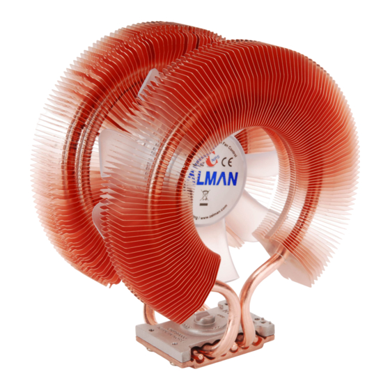
- Page 5 ④ Cooler Orientation In relation to the cooler’s centrally located fan, air flows from the “thinner”(front) heatsink to the “thicker”(rear) heatsink. As shown in the diagram below, it is recommended that the cooler be installed so that air flows from the cooler toward the enclosure’s rear exhaust fan to be released.
- Page 6 ① - Ⓑ Socket 1366 Clip Support Installation Socket 1366 Clip Support Socket 1366 Washer Socket 1366 Clip Support Fixing Bolt (Gold) Warning Socket 1366 Clip Support Fixing Bolts(Gold) must be used. Installation using the Socket 775 Clip Support Fixing Bolts(Silver) can cause damage to the Socket 1366 Clip Support.
- Page 7 ④ Cooler Installation Align the center of the cooler with the center of the CPU, and fix by tightening the bolts on the Clip onto the Clip Support. For easier installation, stabilize the Clip by initially tightening each bolt by one turn or just enough to latch onto the Clip Support’s threading.
- Page 8 3) Installation on AMD Socket AM2+/AM2/754/939/940 ① Thermal Grease Application Clear off any particles or residue from the CPU’s surface then spread (outwards from center) a thin but thorough layer of Thermal Grease on the CPU and the base of the cooler. ②...
- Page 9 ④ Power Connection Please connect the cooler’ s 4-pin connector to the motherboard’ s CPU Fan header. CPU(PWM) Fan header The PWM fan’s operation will vary depending on the motherboard’s BIOS settings. After installation, the PWM Control Mode must be activated in the BIOS. For details regarding PWM Control Mode, please refer to the motherboard’s manual.
Need help?
Do you have a question about the CNPS9900 LED and is the answer not in the manual?
Questions and answers