
Related Manuals for Agilent Technologies U1231A


Summary of Contents for Agilent Technologies U1231A
-
Page 1: Digital Multimeter
Agilent U1231A, U1232A, and U1233A Handheld Digital Multimeter Service Guide Agilent Technologies... -
Page 2: Restricted Rights Legend
U1231-90035 ity and fitness for a particular purpose. age to the product or loss of impor- Agilent shall not be liable for errors or for Edition tant data. Do not proceed beyond a incidental or consequential damages in... -
Page 3: Safety Symbols
AC (Alternating current or voltage) Earth (ground) terminal Caution, risk of danger (refer to this manual for specific Warning or Caution information) Equipment protected throughout by double insulation or reinforced insulation CAT III Category III 600 V overvoltage protection 600 V U1231A/U1232A/U1233A Service Guide... -
Page 4: Safety Considerations
Agilent Technologies assumes no liability for the customer’s failure to comply with these requirements. • Disconnect circuit power and discharge all high-voltage capacitors C A U T I O N before testing resistance, continuity, diodes, or capacitance. - Page 5 • Do not operate the meter with the battery cover or portions of the cover removed or loosened. • To avoid false readings, which may lead to possible electric shock or personal injury, replace the battery as soon as the low battery indicator appears and flashes. U1231A/U1232A/U1233A Service Guide...
-
Page 6: Environmental Conditions
Altitude Up to 2000 meters Pollution degree Pollution degree II The U1231A/U1232A/U1233A Handheld Digital Multimeter complies with the N O T E following safety and EMC requirements: • EN 61010-1 (IEC 61010-1:2001) for CAT III 600 V • ANSI/UL 61010-1:2004 •... - Page 7 The CSA mark is a registered substance elements are expected to trademark of the Canadian Standards leak or deteriorate during normal use. Association. Forty years is the expected useful life of the product. U1231A/U1232A/U1233A Service Guide...
- Page 8 “Monitoring and Control Instrument” product. The affixed product label is as shown below. Do not dispose in domestic household waste. To return this unwanted instrument, contact your nearest Agilent Service Centre, or visit www.agilent.com/environment/product for more information.
- Page 9 Declaration of Conformity (DoC) The Declaration of Conformity (DoC) for this instrument is available on the Agilent website. You can search the DoC by its product model or description at the web address below. http://regulations.corporate.agilent.com/DoC/search.htm If you are unable to search for the respective DoC, please contact your N O T E local Agilent representative.
- Page 10 THIS PAGE HAS BEEN INTENTIONALLY LEFT BLANK. U1231A/U1232A/U1233A Service Guide...
-
Page 11: Table Of Contents
To change the calibration security code To reset the calibration security code to its factory default Using the Front Panel for Adjustments Adjustment considerations Adjustment procedure Valid adjustment input values Functional tests Exiting the adjustment mode Calibration Count Calibration Error Codes U1231A/U1232A/U1233A Service Guide... - Page 12 Service and Maintenance Troubleshooting Checking the Fuse Fuse Replacement Returning the Instrument for Service Replaceable Parts To order replaceable parts Types of Service Available Extended service contracts Obtaining Repair Service (Worldwide) U1231A/U1232A/U1233A Service Guide...
- Page 13 Factory default calibration security code display Figure 1-7 SErn display Figure 1-8 Calibration security code display Figure 1-9 Calibration reference value display Figure 1-10 Vsense functional test Figure 2-1 Testing the fuse Figure 2-2 Replacing the fuse U1231A/U1232A/U1233A Service Guide XIII...
- Page 14 THIS PAGE HAS BEEN INTENTIONALLY LEFT BLANK. U1231A/U1232A/U1233A Service Guide...
- Page 15 List of Tables Table 1-1 Recommended test equipment Table 1-2 Performance verification tests Table 1-3 Adjustment input values Table 1-4 Calibration error codes Table 2-1 Operating checklist Table 2-2 Fuse displayed readings U1231A/U1232A/U1233A Service Guide...
- Page 16 THIS PAGE HAS BEEN INTENTIONALLY LEFT BLANK. U1231A/U1232A/U1233A Service Guide...
-
Page 17: Calibration Procedures
U1231A/U1232A/U1233A Handheld Digital Multimeter Service Guide Calibration Procedures Agilent Calibration Services Closed case calibration Calibration interval Other recommendations for calibration Recommended Test Equipment Basic Operating Test Backlight test Display test Calibration Process Test Considerations Performance Verification Tests Calibration Security Unsecuring the Instrument for Calibration... -
Page 18: Agilent Calibration Services
Calibration Procedures Agilent Calibration Services Agilent Calibration Services When your instrument is due for calibration, contact your local Agilent Service Center for recalibration. See “Types of Service Available” on page 37 for more information on the various calibration services offered. -
Page 19: Other Recommendations For Calibration
Agilent Calibration Services Other recommendations for calibration Specifications are only guaranteed within the specified period from the last calibration. Agilent recommends that readjustment should always be performed at whatever calibration interval you select. This will ensure that the instrument remains within its specifications until the next calibration. -
Page 20: Recommended Test Equipment
Fluke 5520A specification <20% of the instrument accuracy Diode Fluke 5520A specification <20% of the instrument accuracy Temperature Fluke 5520A specification Shorting plug — a dual banana plug with a copper wire Short shorting the two terminals U1231A/U1232A/U1233A Service Guide... -
Page 21: Basic Operating Test
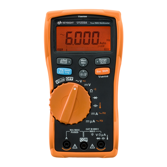
(OFF to ON). Check that all the annunciators are displayed in the LCD. Compare the display with the example shown in Figure 1- 1. Press any key to exit this mode. Figure 1-1 LCD display screen U1231A/U1232A/U1233A Service Guide... -
Page 22: Calibration Process
6 Secure the multimeter against unauthorized calibration; “Exiting the adjustment mode” on page 26. Ensure that the multimeter has quit the adjustment mode and is turned off. 7 Record the new security code and calibration count in the multimeter's maintenance records. U1231A/U1232A/U1233A Service Guide... -
Page 23: Test Considerations
1 hour prior. • Allow a warm- up period of 3 minutes. • Use shielded twisted- pair PTFE- insulated cables to reduce settling and noise errors. Keep the input cables as short as possible. U1231A/U1232A/U1233A Service Guide... -
Page 24: Performance Verification Tests
Performance Verification Tests Use the performance verification tests to verify the measurement performance of the instrument. The performance verification tests use the instrument's specifications listed in the U1231A/U1232A/U1233A User's Guide (available for download at www.agilent.com/find/hhTechLib). The performance verification tests are recommended as acceptance tests when you first receive the instrument. - Page 25 ±0.32 V 600 V 600 V ±3.2 V ±3.2 V ±3.2 V [1] The accuracy is specified after the Null function is used to subtract the thermal effect (by shorting the test leads) before measuring the signal. U1231A/U1232A/U1233A Service Guide...
- Page 26 [5] AC/DC mV measurement must be enabled prior to this step. Refer to the “Enable the AC/DC mV measurement” section of Chapter 4, “Multimeter Setup Options” in the U1231A/U1232A/U1233A User’s Guide for further information on how to enable the AC/DC mV measurement.
- Page 27 600 μA ±6.2 μA ±6.2 μA position. 60 μA 60 μA, 500 Hz ACμA ±0.93μA ±0.93μA While the rotary switch is in the 600 μA 600 μA, 500 Hz ±9.3 μA ±9.3 μA position, press the once. U1231A/U1232A/U1233A Service Guide...
-
Page 28: Calibration Security
The security code is set to “1234” when the instrument is shipped from the factory. The security code is stored in nonvolatile memory, and does not change when power has been turned off. The security code may contain up to 4 numeric characters. U1231A/U1232A/U1233A Service Guide... -
Page 29: Unsecuring The Instrument For Calibration
1 second to enter the calibration security code entry mode. 2 SECU is shown on the display briefly, followed by the calibration security code. Figure 1-2 SECU display Figure 1-3 Calibration security code display U1231A/U1232A/U1233A Service Guide... -
Page 30: Figure 1-4 Calibration Security Code Operation
Press Wrong security code entered. Press Correct security code entered, multimeter enters adjustment mode. Figure 1-4 Calibration security code operation U1231A/U1232A/U1233A Service Guide... -
Page 31: To Change The Calibration Security Code
5 If the new calibration security code has been successfully stored, the display will show PASS. Record down your new calibration security code and store it in a safe location. U1231A/U1232A/U1233A Service Guide... -
Page 32: To Reset The Calibration Security Code To Its Factory Default
4 Press for more than 1 second to enter the calibration security code reset mode. SErn is shown on the display briefly, followed by the calibration security code. Figure 1-7 SErn display Figure 1-8 Calibration security code display U1231A/U1232A/U1233A Service Guide... - Page 33 PASS briefly. The calibration security code is now set to the its factory default code, 1234. If you want to enter a new security code, see “To change the calibration security code” on page 15. Ensure that you record down the new security code. U1231A/U1232A/U1233A Service Guide...
-
Page 34: Using The Front Panel For Adjustments
1 hour with the K- type thermocouple connected. Never turn off the multimeter during an adjustment. This may delete C A U T I O N the calibration memory for the present function. U1231A/U1232A/U1233A Service Guide... -
Page 35: Adjustment Procedure
3. The analog bar graph displays the input reading. There is no bar graph display for temperature adjustment. You are highly recommended to complete the adjustments in the same N O T E order as shown in the appropriate table. U1231A/U1232A/U1233A Service Guide... - Page 36 10 Turn the rotary switch to the next function according to the Test Function column shown in Table 1- 3. Repeat step 3 step 8 for each adjustment point shown in the adjustment table. 11 Verify the adjustments using the “Performance Verification Tests” on page 8. U1231A/U1232A/U1233A Service Guide...
-
Page 37: Valid Adjustment Input Values
Note: Refer to the “Vsense functional test (for U1233A model only)” on page 24. Place the multimeter with the top area as close to the signal source as possible. Ensure that the calibrator’s Earth function is turned on. U1231A/U1232A/U1233A Service Guide... - Page 38 (Scale/ 0.9 to 1.1 × Reference value 600 mV 600.0 mV Transducer) 0.9 to 1.1 × Reference value ACmV 30.0 mV (70 Hz) (Scale/ 600 mV 0.9 to 1.1 × Reference value 600.0 mV (70 Hz) Transducer) U1231A/U1232A/U1233A Service Guide...
- Page 39 0.7 to 1.3 × Reference value 0.300 A (70 Hz) 0.7 to 1.3 × Reference value 6.000 A (70 Hz) 0.7 to 1.3 × Reference value 3.00 A (70 Hz) 10 A 0.7 to 1.3 × Reference value 10.00 A (70 Hz) U1231A/U1232A/U1233A Service Guide...
-
Page 40: Functional Tests
1 Connect the COM and Ω terminals of the U1252B (or equivalent) to the COM and V terminals of the multimeter under test. 2 Turn the U1231A/U1232A/U1233A rotary switch to the position before proceeding with the following Z functional test. -
Page 41: Figure 1-10 Vsense Functional Test
Press and hold for more than 1 second. 5 V, 55 Hz No alert Lo.SE 15 V, 55 Hz Alert on 3 Adjustment or repair is required if the multimeter fails any of the Vsense functional test. U1231A/U1232A/U1233A Service Guide... -
Page 42: Exiting The Adjustment Mode
1 Remove all the shorting plugs and connectors from the instrument. 2 Record the new Calibration Count. 3 Press simultaneously to exit the Adjustment Mode. 4 Power off and on again. The instrument will then be secured. U1231A/U1232A/U1233A Service Guide... -
Page 43: Calibration Count
2 Take note of the calibration count to keep track of the number of calibrations that have been performed. 3 Press and hold for more than 1 second again to exit the calibration count mode. U1231A/U1232A/U1233A Service Guide... -
Page 44: Calibration Error Codes
Calibration error: serial number code invalid Er004 Calibration error: calibration aborted Er005 Calibration error: value out of range Er006 Calibration error: signal measurement out of range Er007 Calibration error: frequency out of range Er008 EEPROM write failure U1231A/U1232A/U1233A Service Guide... - Page 45 U1231A/U1232A/U1233A Handheld Digital Multimeter Service Guide Service and Maintenance Troubleshooting Checking the Fuse Fuse Replacement Returning the Instrument for Service Replaceable Parts To order replaceable parts Types of Service Available Extended service contracts Obtaining Repair Service (Worldwide) This chapter will help you troubleshoot a failing instrument.
-
Page 46: Troubleshooting
U1233A models only) page 31). ❏ Verify the optical side of of the IR-USB cable connected to multimeter — the Agilent logo should be facing up. ❏ Verify the baud rate, data bit, stop bit, and Failed on remote control parity settings in the multimeter’s Setup... -
Page 47: Service And Maintenance
Replace the fuse when OL is displayed. Table 2-2 Fuse displayed readings Displayed readings Current input Part number Fuse rating terminal Fuse healthy Replace fuse ≈0.0 Ω 2110-1402 11 A/1000 V U1231A/U1232A/U1233A Service Guide... -
Page 48: Figure 2-1 Testing The Fuse
Service and Maintenance Checking the Fuse Figure 2-1 Testing the fuse U1231A/U1232A/U1233A Service Guide... -
Page 49: Fuse Replacement
Replace a new fuse of the same size and rating into the center of the fuse holder. 3 Close the batter cover. Place the battery cover back in its original position and tighten the screws. U1231A/U1232A/U1233A Service Guide... -
Page 50: Figure 2-2 Replacing The Fuse
Service and Maintenance Fuse Replacement Figure 2-2 Replacing the fuse U1231A/U1232A/U1233A Service Guide... -
Page 51: Returning The Instrument For Service
Returning the Instrument for Service Before shipping your instrument for repair or replacement, Agilent recommends that you acquire the shipping instructions from the Agilent Technologies Service Center. A clear understanding of the shipping instructions is necessary to secure your product for shipment. -
Page 52: Replaceable Parts
To order replaceable parts from Agilent, do the following: 1 Contact your nearest Agilent Sales Office or Service Center. 2 Identify the parts by the Agilent part number shown in the support parts list. 3 Provide the instrument model number and serial number. -
Page 53: Types Of Service Available
Service and Maintenance Types of Service Available Types of Service Available If your instrument fails during the warranty period, Agilent Technologies will repair or replace it under the terms of your warranty. Extended service contracts Many Agilent products are available with optional service contracts that extend the covered period after the standard warranty expires. -
Page 54: Obtaining Repair Service (Worldwide)
To obtain warranty, service, or technical support information you can contact Agilent Technologies at one of the following telephone numbers: • In the United States: (800) 829- 4444 • In Europe: 31 20 547 2111 •... - Page 55 (tel) 0800 047 866 (fax) 0800 286 331 Other Asia Pacific Countries: (tel) (65) 6375 8100 (fax) (65) 6755 0042 Or visit Agilent World Wide Web at: www.agilent.com/find/assist Product specifications and descriptions in this document are subject to change without notice. Always refer to Agilent Web site for the latest revision.