
Related Manuals for Agilent Technologies U1242A


Summary of Contents for Agilent Technologies U1242A
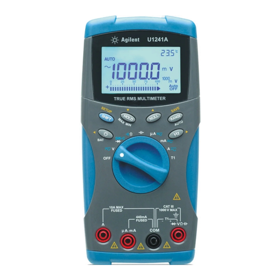
- Page 1 Agilent U1241A and U1242A Handheld Digital Multimeters User’s and Service Guide Agilent Technologies...
-
Page 2: Restricted Rights Legend
Notices Warranty Safety Notices © Agilent Technologies, Inc., 2007 – 2012 No part of this manual may be reproduced in The material contained in this docu- any form or by any means (including elec- ment is provided “as is,” and is sub-... -
Page 3: Safety Symbols
Safety Symbols The following symbols on the instrument and in the documentation indicate precautions which must be taken to maintain safe operation of the instrument. Direct current (DC) Off (supply) Alternating current (AC) On (supply) Both direct and alternating current Caution, risk of electric shock Caution, risk of danger (refer to this manual Three-phase alternating current... -
Page 4: General Safety Information
General Safety Information The following general safety precautions must be observed during all phases of operation, service and repair of this instrument. Failure to comply with these precautions or with specific warnings elsewhere in this manual violates safety standards of design, manufacture and intended use of the instrument. Agilent Technologies assumes no liability for the customer’s failure to comply with these requirements. - Page 5 If necessary, return the product to Agilent Technologies Sales and Service Office for service and repair to ensure the safety features are maintained. •...
- Page 6 Environment Conditions This instrument is designed for indoor in the area with low condensation and use with standard or compatible test probes. Table 1 shows general environment requirements. Table 1 Environment Requirements Environment Conditions Requirements Operating environment Full accuracy at –10 °C to 55 °C Operating relative humidity Full accuracy up to 80% RH for temperature up to 30 °C, decreasing...
- Page 7 Regulatory Markings The CE mark is a registered trademark The C-tick mark is a registered trademark of the European Community.This CE of the Spectrum Management Agency of mark shows that the product complies Australia. This signifies compliance with with all the relevant European Legal the Australia EMC Framework Directives.
- Page 8 Waste Electrical and Electronic Equipment (WEEE) Directive 2002/96/EC This instrument complies with the WEEE Directive (2002/96/EC) marking requirement. This affixed product label indicates that you must not discard this electrical/electronic product in domestic household waste. Product Category: With reference to the equipment types in the WEEE directive Annex 1, this instrument is classified as a “Monitoring and Control Instrument”...
-
Page 9: In This Guide
In This Guide… Getting Started Chapter 1 introduces key features and steps to get started with a U1241A or U1242A handheld digital multimeter. This chapter also guides you through the basics of the front panel operations. Features and Functions Chapter 2 contains the information on how to set up connections to perform meter measurements. - Page 10 Declaration of Conformity (DoC) The Declaration of Conformity (DoC) for this instrument is available on the Web site. You can search the DoC by its product model or description. http://regulations.corporate.agilent.com/DoC/search.htm If you are unable to search for the respective DoC, please contact your N O T E local Agilent representative.
-
Page 11: Table Of Contents
Contents Getting Started Introduction Checking the Shipping Contents The Front Panel at a Glance Adjusting Tilt Stand The Annunciator at a Glance Analog Bar Graph The Keypad and Rotary Switch at a Glance The Input Terminal at a Glance Features and Functions Measuring Voltage Measuring Current (>... - Page 12 Refresh Hold NULL (Relative) Data Logging (U1242A) Manual Logging Interval Logging Reviewing Logged Data Removing Logged Data Scanning Temperature Measurement (U1242A) Checking Battery Capacity Alerts and Warning During Measurement Overload Alert Input-A Warning Alert Input-mA Warning Alert Default Setting Configurations Setting Configurations Service and Maintenance General Maintenance...
- Page 13 Recommended Test Equipment Basic Operating Test Backlight Test Testing the Display Input-A Terminal Test Input-mA Terminal Alert Test Calibration Process Test Considerations Input Connections Performance Verification Tests Calibration Security Unsecuring the Meter for Calibration Using the Front Panel for Adjustments Adjustment Considerations Valid Adjustment Input Values Calibration Adjustments...
- Page 14 Harmonic Ratio Specifications Frequency Specifications Frequency Sensitivity During Voltage Measurement[2] Frequency Sensitivity During Current Measurement[3] Operating Specifications General Characteristics U1241A/U1242A User’s and Service Guide...
- Page 15 The Keypad and Rotary Switch at a Glance The Input Terminal at a Glance This chapter introduces key features and steps to get started with a U1241A or U1242A handheld digital multimeter. This chapter also guides you through the basics of the front panel operations. Agilent Technologies...
-
Page 16: Introduction
Getting Started Introduction The handheld digital multimeters’ key features are: • DC, AC voltage and current measurements. • True- RMS measurement for both AC voltage and current • Harmonic ratio for power quality of sine wave (for U1242A) • Switch counter for detecting the bounce of switch •... -
Page 17: Getting Started
If any of the above item missing, or any mechanical damage and defect on the meter, notify your nearest Agilent Technologies Sales Office. Table 1-1 List of standard items and optional accessories... -
Page 18: The Front Panel At A Glance
Getting Started The Front Panel at a Glance Annunciator Keypad Rotary Switch Input Terminal Figure 1-1 Front panel of a U1241A and U1242A handheld digital multimeters Adjusting Tilt Stand Tilt stand at 60° Tilt stand at 30° Bend the tip of the stand Pull the tilt stand outwards to its maximum reach (approximately 60°) Figure 1-2 Tilt stand positions... -
Page 19: The Annunciator At A Glance
Getting Started The Annunciator at a Glance To view the full display, press and hold while turning the rotary switch from OFF to any non- OFF position. Press any key to resume normal functionality mode. Figure 1-3 Annunciator display of a U1242A handheld digital multimeter Table 1-2 Descriptions of each annunciator Descriptions Descriptions... -
Page 20: Analog Bar Graph
Getting Started Analog Bar Graph When frequency is indicated on the primary display during voltage or cur- rent measurement, the bar graph represents the voltage or current value. When 4–20 mA% scale or 0–20 mA% scale is indicated on the primary dis- play, the bar graph represents the current value. -
Page 21: Getting Started
Getting Started Table 1-4 Keypad descriptions and functions Function First level functions Range Second level functions (press ..) Range Turn off the meter DCV measurement 0.1 mV to 1000 V ACV measurement 0.1 mV to 1000 V Harmonic ratio (for U1242A only) 0.0% to 99.9% Diode measurement Switch counter measurement... -
Page 22: The Input Terminal At A Glance
Getting Started The Input Terminal at a Glance To avoid damaging this device, do not exceed the input limit. WA R N I N G Figure 1-5 Input terminal of a U1242A handheld digital multimeter Table 1-6 Terminal connections for different measuring functions Measurement Functions Input terminal Overload Protection... -
Page 23: Features And Functions
Alerts and Warning During Measurement This chapter contains the detail information on how to configure connections to perform the meter measurements using the U1241A and U1242A handheld digital multimeters. It builds on information you learned in the Quick Start Guide. Agilent Technologies... -
Page 24: Measuring Voltage
2 Features and Functions Measuring Voltage Ensure that terminal connections are correct for that particular measurement before any WA R N I N G measurement. To avoid damaging the device, do not exceed the input limit. Measuring DC Voltage Measuring AC Voltage Press to select (U1241A) or... -
Page 25: Measuring Current (< 440 Ma)
Features and Functions 2 Measuring Current (< 440 mA) If the measured value is lower than 440 mA, use the mA or μA current measurement mode. N O T E Press to select AC current measurement mode. Measuring % Scale of 4 – 20 mA The % scale of 0 –... -
Page 26: Measuring Frequency
2 Features and Functions Measuring Frequency The frequency measurement is applicable for DC and AC current measurements. Press (U1241A) or The bar graph is used to indicate the value of AC voltage. Alternatively, (U1242A) press button to display the position value of AC voltage. -
Page 27: Testing Diodes
Features and Functions 2 Press button to select measurement range from 1 kW to 100 MW. N O T E Testing Diodes Disconnect circuit power and discharge all high-voltage capacitors before testing diodes to C A U T I O N prevent possible damage to the meter. -
Page 28: Measuring Capacitance
2 Features and Functions Measuring Capacitance Disconnect circuit power and discharge all high-voltage capacitors before measuring C A U T I O N capacitance to prevent possible damage to the meter or the device under test. To confirm that capacitors have discharged, use the DC voltage function. Measuring tips: •... - Page 29 Features and Functions 2 Measuring tips: • Clean the measurement surface and remember to disable the applied power. • When measuring temperature, move the thermocouple along the surface Press until you get the highest/lowest T1T2 (U1242A) temperature reading. position to •...
-
Page 30: Measuring Harmonic Ratio (U1242A)
2 Features and Functions Measuring Harmonic Ratio (U1242A) Harmonics ratio function indicates the deviation of non- sinusoidal to sinusoidal waveform from the range of 0% to 100%. A pure sinusoidal Press waveform without harmonics gives a value of 0.0%. position Alternatively, press button to display the RMS value of AC voltage. - Page 31 Features and Functions 2 1 Remove the power on the contacts or switch before measured. 2 Press position to activate the switch counter function. The meter will detect the switch condition as shown in Table 2- Table 2-7 Annunciator display for each switch condition Switch Condition Circuit Switch Display...
-
Page 32: Minmax Recording
2 Features and Functions MINMAX Recording 1 Press for more than one second to enter MINMAX Recording mode. Meter is now in continuous mode or non- data hold (non- trigger) mode. 2 The beeper sounds when a new maximum or minimum value is recorded. -
Page 33: Refresh Hold
Features and Functions 2 Refresh Hold Users are required to activate the Refresh Hold in the setup mode. 1 Press to enter Refresh Hold mode. The present value will be held, and the annunciator is displayed. 2 The meter is ready to hold new measuring value once the variation of measuring value exceeds the setting of variation count, and the annunciator is flashed. -
Page 34: Data Logging (U1242A)
2 Features and Functions • In resistance measurement, the meter reads a non-zero value due to the presence of N O T E test leads resistance. Use the Null function to zero-adjust the effect of test lead resistance. • In DC voltage measurement, the thermal effect will influence the accuracy. Short the test leads and press once the displayed value is stable in order to zero out the offset. -
Page 35: Manual Logging
Features and Functions 2 Manual Logging To enable the Hand (manual) logging function, select the Hand logging mode in Setup mode. 1 Press (Log) for more than one second to store the present value and function on primary display to memory. 2 Press (Log) again for the next value that you want to save into memory, see... -
Page 36: Reviewing Logged Data
2 Features and Functions When interval (automatic) logging is enabled, all keypad operation is disabled, except for N O T E LOG function. Figure 2-7 Interval logging display Maximum data that can be stored is 200 entries. When the 200 entries are filled, FUL N O T E annunciator is indicated on the secondary display. -
Page 37: Scanning Temperature Measurement (U1242A)
Features and Functions 2 Scanning Temperature Measurement (U1242A) This scanning temperature measurement function allows users to measure and display temperature T1, T2 and T1- T2 sequentially. 1 Press and hold (SCAN) button for more than one second to enable SCAN mode. Notice the meter will scan through and display the value of T1, T2 and T1- T2 periodically. -
Page 38: Alerts And Warning During Measurement
2 Features and Functions Alerts and Warning During Measurement Overload Alert For your safety, please be aware of the alert. When you are alerted, just remove the test WA R N I N G leads from the measuring source. The meter provides an overload alert for voltage measurement in both auto and manual range modes. -
Page 39: Default Setting Configurations
U1241A and U1242A Handheld Digital Multimeter User’s and Service Guide Default Setting Configurations Setting Configurations This chapter describes on how to change and configure the default setting of U1241A and U1242A handheld digital multimeters including data logging and other setting features. Agilent Technologies... -
Page 40: Setting Configurations
Default Setting Configurations Setting Configurations 1 Turn meter OFF. 2 From OFF position, press and hold (SETUP) while turning the rotary switch to any non- OFF position. After you hear a beep, the meter is in Setup mode and you can release button. - Page 41 Default Setting Configurations Table 3-9 Available setting options in Setup mode Menu item Available setting options Default factory setting Setup Selection Description Description Enables Data Hold (manual trigger) Trigger hold 100–1000 Sets variation count that determines Refresh Hold (auto trigger) 0–20 mA, Sets % scale readout for 0 to 20 mA or 4 to 20 mA 4–20 mA...
- Page 42 Default Setting Configurations Available setting options Default factory Menu item setting Setup Display Description Description d-CF Sets temperature measurement to °C, pressing d-CF Temperature to change measurement unit to °F Sets temperature measurement to °F d-FC Sets temperature measurement to °F, pressing to change measurement unit to °C Sets temperature measurement to °C [1] To activate the meter after it has auto power off, press any button to resume back to respective...
-
Page 43: Service And Maintenance
This chapter provides you with warranty services, maintenance procedures and troubleshooting hints to solve general problems that you may encounter with the instrument. Repair or service which are not covered in this manual should only be performed by qualified personnel. Agilent Technologies... -
Page 44: General Maintenance
Service and Maintenance General Maintenance To avoid electrical shock or damage to the meter, ensure no water stays inside the WA R N I N G casing. Besides the above hazard, dirt or moisture in the terminals can distort readings. Cleaning steps are as follows: 1 Turn the meter off and remove the test leads. -
Page 45: Fuse Replacement
Service and Maintenance 3 Lift and remove the battery cover to the direction of screw. 4 Replace the specified batteries, ensure the correct polarity of batteries. 5 Reverse the procedures of opening the cover to close the battery cover. Battery Types ANSI/NEDA Alkaline LR03... - Page 46 Service and Maintenance 3 Gently remove the defective Fuse 1 by prying one end of the fuse and removing it out of the fuse bracket, see Figure 4- 4 Replace a new fuse of the same size and rating into the center of the fuse holder.
-
Page 47: Troubleshooting
Service and Maintenance 8 Ensure that the rotary switch position is aligned with the align marking on the top case and circuit board switch stay on the OFF position. 9 Then re- fasten the circuit board and the bottom cover respectively. Troubleshooting To avoid electrical shock, do not perform any service unless you are qualified to do so. -
Page 48: Returning Instrument For Service
You are recommended to use the original shipping material or order materials from an Agilent Technologies Sales Office. If both options are not available, place 8 to 10 cm (3 to 4 inches) of shock- absorbing and static- free packaging material around the instrument to avoid movement during shipping. - Page 49 Calibration Count Calibration Errors This chapter contains procedures of performance verification tests and calibration adjustments. The performance tests is meant to verify the U1241A or U1242A handheld digital multimeter to ensure the meter is operating within its published specifications. Agilent Technologies...
-
Page 50: Performance Tests And Calibration
Performance Tests and Calibration Calibration Overview Ensure that you have read Test Considerations before calibrating the meter. N O T E Closed-case Electronic Calibration The meter features closed- case electronic calibration. No internal mechanical adjustments are required. The meter calculates correction factors based upon the input reference value you set. -
Page 51: Adjustment Is Recommended
Performance Tests and Calibration Adjustment is Recommended Specifications are only guaranteed within the period stated from the last adjustment. Whatever calibration interval you select, Agilent recommends that complete re- adjustment should always be performed at the calibration interval. This will assure that the U1241A/U1242A will remain within specification for the next calibration interval. -
Page 52: Recommended Test Equipment
Performance Tests and Calibration Recommended Test Equipment The test equipment recommended for the performance verification and adjustment procedures is listed below. If the exact equipment is not available, substitute the calibration standards of equivalent accuracy. Table 5-12 Recommended test equipment Application Recommended Equipment Recommended Accuracy Requirements... -
Page 53: Basic Operating Test
Performance Tests and Calibration Basic Operating Test Basic Operating Test is used to test the basic operability of the meter. Repair is required if the meter fails the Basic Operating Test. Backlight Test To test the backlight function, press momentarily to turn backlight ON at medium level of brightness intensity. -
Page 54: Input-A Terminal Test
Performance Tests and Calibration Input-A Terminal Test This test determines if the input warning of the A current terminal test is functioning properly. The meter sounds an alerting beep when the test lead is inserted to the A input terminal but the rotary switch is not set to the corresponding A location. -
Page 55: Test Considerations
Performance Tests and Calibration Test Considerations Error may be induced by AC signals that present on the input leads. Long test leads can also act as an antenna causing pick- up of AC signals. For optimum performance, all procedures should comply with the following recommendations: •... -
Page 56: Input Connections
Performance Tests and Calibration Input Connections Test connections to the meter are best accomplished using the K- type thermocouple wire and mini- connectors for temperature measurement. The J- type thermocouple wire and mini- connectors can also be used for temperature measurements (for U1242A). Shielded, twisted- pair, PTFE interconnect cables of minimum length are recommended between the calibrator and the meter. - Page 57 Performance Tests and Calibration Table 5-13 Verification Tests Error from nominal 1 year Step Test Function Range 5520A Output U1241A U1242A Turn the rotary switch to 1000 mV 1000.0 mV ± 1.4 mV position 10 V 10.000 V ± 11 mV 100 V 100.00 V ±...
- Page 58 Performance Tests and Calibration Error from nominal 1 year Step Test Function Range 5520A Output U1241A U1242A 1000 W 1000.0 W ± 3.3 W Turn the rotary switch to position ± 33 W 10 kW 10.000 kW ± 330 W 100 kW 100.00 kW 1000 kW...
- Page 59 Performance Tests and Calibration Error from nominal 1 year Step Test Function Range 5520A Output U1241A U1242A Turn the rotary switch to position 10 A 10.000 A ± 65 mA Press to go to function 10 A 10.000 A , 500 Hz ±...
-
Page 60: Calibration Security
Performance Tests and Calibration Calibration Security The calibration security code prevents accidental or unauthorized adjust- ments to the meter. The meter is secured when the meter is shipped from factory. Before performing any adjustment to the meter, you are required to unsecure the meter by entering the correct security code (see Unsecur- ing the Meter for... - Page 61 Performance Tests and Calibration “E02” on the secondary display for approximately 3 seconds and return to the Calibration Security entry mode. Changing the Meter Calibration Security Code from the Front Panel 1 When the meter is in the unsecured mode, press button for more than one second to enter Calibration Security Code setting mode.
-
Page 62: Using The Front Panel For Adjustments
Performance Tests and Calibration 6 Set the code, same as the last 4 digit serial number of the meter. Press (Save) to confirm the entry. 7 If the 4 digit serial number entered is correct, the secondary display will show PAS. If an invalid code is entered, the meter will shows error code E03. -
Page 63: Adjustment Considerations
Performance Tests and Calibration Adjustment Considerations After each adjustment, the secondary display shows PAS. If the calibration fails, the meter N O T E sounds a beep, and an error number is shown in the secondary display. Calibration error messages are described in Calibration Errors. -
Page 64: Valid Adjustment Input Values
Performance Tests and Calibration Valid Adjustment Input Values Adjustment can be accomplished using the following input values below. Table 5-14 Valid adjustment input values Function Range Valid Input Reference Values 1000 mV, 10 V, 100 V, 1000 V 0.9 to 1.1 x Full Scale 1000 mV, 10 V, 100 V, 1000 V 0.9 to 1.1 x Full Scale 0.9 to 1.1 x Full Scale... -
Page 65: Calibration Adjustments
Performance Tests and Calibration Calibration Adjustments Review the Test Considerations Adjustment Considerations before beginning the N O T E adjustment procedures. 1 Turn the rotary switch to Test Function position, as shown in Table 5- 2 After unsecuring the meter, the meter will go into the adjustment mode, Unsecuring the Meter for Calibration. - Page 66 Performance Tests and Calibration 9 Turn the rotary switch to the next function according to the Test Function column shown in Table 5- 14. Repeat steps 3 to 8 for each adjustment point shown in the calibration adjustment, see Table 5- 10 Verify the adjustments using the Performance Verification Tests.
- Page 67 Performance Tests and Calibration Step Test Function Cal Range Input Cal Item U1241A U1242A Turn the rotary switch to Short Dual banana plug with SHrt position copper wires short between two terminals 1.000 V Turn the rotary switch to Short Dual banana plug with SHrt position...
- Page 68 Performance Tests and Calibration Step Test Function Cal Range Input Cal Item U1241A U1242A Turn the rotary switch to Open Input terminals open oPEn μA position (remove all test leads and shorting plugs from input terminals) 1000 μA 1000 μA 1000.0 μA 10000 μA 10000 μA...
-
Page 69: Exiting Adjustment Mode
Performance Tests and Calibration Step Test Function Cal Range Input Cal Item U1241A U1242A Move the test lead from “μA.mA” and “COM” terminal to “A” and “COM” terminal Caution: Connect the calibrator to the meter's “A” and “COM” terminal before applying 10 A Turn the rotary switch to Open Input terminals open... -
Page 70: Calibration Count
Performance Tests and Calibration Calibration Count The meter provides the calibration count information for users to access through front panel operation. Note that the meter was calibrated prior to shipping out to users. Users are recommended to record the initial value of the calibration count once receiving the meter. -
Page 71: Specifications And Characteristics
U1242A handheld digital multimeters. These specifications apply when using the meter in an environment that is free of electromagnetic interference and electrostatic charge. When using the meter in an environment where electromagnetic interference or significant electrostatic charge is present, measurement accuracy may be reduced. Agilent Technologies... -
Page 72: Dc Specifications
Specifications and Characteristics DC Specifications Table 6-17 DC specifications with accuracy of ± (% of reading + No. of Least Significant Digit) Test Current/ Accuracy Function Range Resolution Burden Voltage U1241A U1242A 1000.0 mV 0.1 mV 0.09% + 5 Voltage 10.000 V 0.001 V 0.09% + 2... -
Page 73: Ac Specifications
Specifications and Characteristics AC Specifications Table 6-18 AC specifications with accuracy of ± (% of reading + No. of Least Significant Digit) Test Current/ Accuracy Function Range Resolution Burden Voltage 40 Hz to 500 Hz 500 Hz to 1 kHz 1 kHz to 2 kHz 1000.0 mV 0.1 mV... -
Page 74: Resistance Specifications
Specifications and Characteristics Resistance Specifications Table 6-19 Resistance specifications with accuracy of ± (% of reading + No. of Least Significant Digit) Function Test Current/ Accuracy Range Resolution Burden Voltage 0.1 Ω 0.5 mA 1000.0 Ω Resistance 50 μA 0.001 kΩ 10.000 kΩ... -
Page 75: Temperature Specifications
Specifications and Characteristics Temperature Specifications Table 6-21 Temperature specifications with accuracy of ± (% of reading + offset error) Function Thermocouple Type Range Resolution Accuracy –40 °C to 1000 °C 0.1 °C 1% + 1°C Temperature –40 °F to 1832 °F 0.1 °F 1%+ 1.8 °F –40 °C to 1000 °C... -
Page 76: Capacitance Specifications
Specifications and Characteristics Capacitance Specifications Table 6-22 Capacitance specifications with accuracy of ± (% of reading + No. of Least Significant Digit) Function Range Resolution Accuracy 1000.0 nF 0.1 nF 1.2 % + 4 Capacitance 10.000 μF 0.001 μF 100.00 μF 0.01 μF 1000.0 μF 0.1 μF... - Page 77 Specifications and Characteristics [2] Pure sinusoidal waveforms without harmonics have a harmonics ratio of 0%, higher the harmonics ratio, more harmonics are present in the sinusoidal waveform. U1241A/U1242A User’s and Service Guide...
-
Page 78: Frequency Specifications
Specifications and Characteristics Frequency Specifications Table 6-24 Freq uency specifications with accuracy of ± (% of reading + No. of Least Significant Digit) Function Range Resolution Accuracy Min. Input Frequency Frequency 100.00 Hz 0.01 Hz 0.03% + 3 1 Hz 1000.0 Hz 0.1 Hz 10.000 kHz... -
Page 79: Operating Specifications
Specifications and Characteristics Operating Specifications Table 6-25 Measuring rate of U1241A and U1242A Function Times/second DCV (V or mV) Ω Diode 4 (< 100 μF) Capacitance DCA (μA, mA, A) ACA (μA, mA, A) Temperature 7 (single) Frequency 1 (>10 Hz) U1241A/U1242A User’s and Service Guide... -
Page 80: General Characteristics
Specifications and Characteristics General Characteristics Table 6-26 General characteristics of U1241A and U1242A Power Supply • 4 single standard 1.5 V AAA batteries (Alkaline or Zinc Chloride type) Display • Dual display (secondary display is cater for temperature function display only) are 4-digit liquid crystal display (LCD) with maximum reading of 11,000 counts. - Page 81 Specifications and Characteristics Weight • 450 g with batteries • 400 g without batteries Warranty • Please refer to http://www.agilent.com/go/warranty_terms • Three years for the product • Three months for the product's standard accessories, unless otherwise specified • Please take note that for the product, the warranty does not cover: •...
- Page 82 Specifications and Characteristics U1241A/U1242A User’s and Service Guide...
- Page 83 Index Index EMC, key features, accuracy, Entering Adjustment Values, adjustments, Environment, Altitude, VI, moisture, flammable, battery, FRAGILE, NMRR, Frequency, nominal, Front Panel Normal, Adjustments, Calibration fumes, Overview, calibrator, Operating, VI, Capacitance, Overload, Category, General, Characteristics, CMRR, paragraph tags, 2, 10, Harmonic Ratio, Coefficient, polarity,...
- Page 84 Index Storage, symbols, tags paragraphs, 2, 10, Temperature, Test Considerations, Equipment, test probes, Using the Front Panel for Adjustments, Vibration, Warm Up Period, Calibration, Warranty, WEEE, VIII Weight, U1241A/U1242A User’s and Service Guide...
- Page 85 (fax) (65) 6755 0042 Or visit Agilent worldwide web at: www.agilent.com/find/assist Product specifications and descriptions in this document subject to change without notice. © Agilent Technologies, Inc. 2007 – 2012 Printed in Malaysia Seventh Edition, May 4, 2012 U1241-90003 Agilent Technologies...