
Related Manuals for Grecom PSR-300


Summary of Contents for Grecom PSR-300
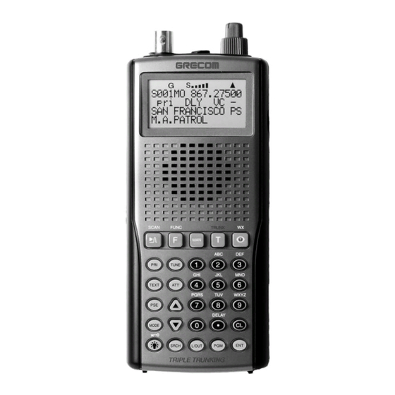
- Page 1 PSR-300 1,000 Channel Triple Trunking Hand Held Scanner Please read this user’s guide before installing, setting up and using your new product. Owner’s Manual...
-
Page 2: Table Of Contents
CONTENTS FEATURES ........................4 PREPARATION ......................7 Power Sources ......................7 Using Batteries ......................7 Charging Rechargeable Batteries ................8 Using AC Power ....................... 9 Using Vehicle Battery power .................. 10 Connecting Supplied Antenna ..................11 Connecting an Outdoor Antenna ................11 Connecting Earphone/Headphone ................ - Page 3 Turning Channel-Storage Banks Off and On ............... 38 Monitoring a Single Channel/Power Save Circuit ............38 Using CTCSS and DCS ....................39 Deleting Frequencies from Channels ................39 Deleting All Frequencies in a Channel bank ..............39 Using Delay ......................... 40 Locking Out Channels or Frequencies ...............
-
Page 4: Features
SAME/FIPS Weather Alert – displays the weather event for the specific cities or counties you choose so you can hear the alert tone. Data Cloning – lets you transfer the programmed data to another PSR-300/ 400 scanner. You can also upload or download the programmed data to or from a PC using an optional USB Scanner/PC Interface Cable. -
Page 5: The Fcc Wants You To Know
Supplied Flexible Antenna with BNC Connector – provides good reception of strong local signals. You can connect an external antenna with a BNC con- nector to the scanner for improved reception of distant/weaker signals. Memory Backup – keeps the frequencies stored in memory for an extended time even without internal batteries. -
Page 6: Scanning Legally
SCANNING LEGALLY Your scanner covers frequencies used by many different groups including po- lice and fire departments, ambulance services, government agencies, private companies, amateur radio, military operations, pager services, and wireline (telephone and telegraph) service providers. It is legal to listen to almost every transmission your scanner can receive. -
Page 7: Preparation
PREPARATION POWER SOURCES You can power your scanner from any of three sources: • internal non-rechargeable batteries or rechargeable batteries (not supplied – see “Using Batteries”). • standard AC power (with a supplied AC adaptor – see ”Using AC Power” on Page 9). -
Page 8: Charging Rechargeable Batteries
• Do not mix old and new batteries, different types of batteries (alkaline, or rechargeable), or rechargeable batteries of different capacities. • If you do not plan to use the scanner with batteries for a month or longer, remove the batteries. Batteries can leak chemicals that can destroy elec- tronic parts. -
Page 9: Using Ac Power
USING AC POWER You can power the scanner using a supplied AC adaptor. Cautions: ! You must use a supplied AC adaptor. • Always connect the AC adaptor to the scanner before you connect it to AC power. When you finish, disconnect the adaptor from AC power before you disconnect it from the scanner. -
Page 10: Connecting An Outdoor Antenna
CONNECTING THE SUPPLIED ANTENNA To attach the supplied flexible antenna to the antenna jack on top of your scan- ner, align the slots around the antenna’s connector with the tabs on the an- tenna jack. Press the antenna down over the jack and turn the antenna’s base clockwise until it locks into place. -
Page 11: Connecting Supplied Antenna
To remove the belt clip, pull the tab out and slide the clip upward. Transferring Data to or from Another Scanner or PC You can transfer the programmed data to and from another PSR-300 (or PSR- 400) scanner using an optional connecting cable which has 1/8-inch stereo (TRS) phone plugs on both ends. -
Page 12: Your Scanner's Controls
YOUR SCANNER’S CONTROLS SCAN/ – scans through the programmed channel, or activates the Spec- trum Sweeper function. FUNC (function) – lets you use various functions by pressing this key in combi- nation with other keys. MAN – stops scanning and lets you directly enter a channel number. TRUNK –... - Page 13 PGM (Program) – programs frequencies into channels. ENT – completes the entry of frequencies and text. 1 – enters a 1, or inputs characters 0 through 9 in text mode. 2/ABC – enters a 2, or inputs characters A, B, or C. 3/DEF –...
-
Page 14: Quick Start
QUICK START To help familiarize yourself with the scanner’s functions, keypad, and available frequencies, you can utilize one of these four features before you begin pro- gramming the scanner. Spectrum Sweeper – searches nearby strong signals quickly. See “Spectrum Sweeper”. Preprogrammed Search Banks –... - Page 15 (FM) with Continuous Tone Coded Squelch System (CTCSS) subaudible tone codes. CTCSS allows multiple users to share a single radio frequency without hearing each other’s transmissions. In your PSR-300 scanner, the CTCSS feature can be used to block the reception of transmissions on shared...
- Page 16 Motorola trunking systems come in three categories: Type I, Type II, and Type I/II Hybrid. Each category displays and uses talkgroup IDs in slightly different ways. Motorola Type II IDs are in the form FFF-SS, where; FFF=Fleet ID SS=Subfleet ID Type I systems are usually organized with different user groups assigned to different fleets.
- Page 17 EDACS (ED) mode You can set your scanner so it decodes the talkgroup IDs used with EDACS (invented by GE/Ericsson) trunking systems. This setting is called the EDACS mode. EDACS systems are trunking systems used primarily by business or private communications service providers, as well as by some public safety organiza- tions.
- Page 18 HR order, starting with Memory X01 in the selected bank. Your PSR-300 scanner features a new tool to help you determine the correct channel mapping for LTR system frequencies. The scanner’s LTR Repeater Finder displays the current Home Repeater when monitoring LTR transmis- sions in manual mode.
-
Page 19: Open And Closed Modes
Open and Closed Modes You can set your scanner to change the way it receives signals. These settings, called open mode and closed mode, affect how the scanner receives signals from communications systems that use some type of closed squelch (such as Motorola, EDACS, and LTR systems). -
Page 20: Setting Up Your Scanner
SETTING UP YOUR SCANNER Turning on the Scanner and Setting Squelch 1. To turn on the scanner, turn VOL clockwise. Welcome to Scanning Receiver appears. After about 3 seconds, you might hear a hissing sound. Then ad- just VOL to a comfortable level. 2. - Page 21 Notes: • Press FUNC. Then press . The bank number moves in the direction of the arrow pressed. • Press FUNC. Then hold down . The bank number moves continu- ously in the assigned direction. • Press . The channel number moves upward one by one. Or, press .
-
Page 22: Ctcss And Dcs
CTCSS AND DCS Your PSR-300 scanner features CTCSS and DCS decoder. CTCSS and DCS allow you to program frequencies into your scanner that are used by more than one group in your area and listen only to the group that is of interest to you by specifying the group’s specific CTCSS or DCS code. - Page 23 Note: CTCSS, DCS and digital voice all operate independently of each other. If a channel is configured for CTCSS or DCS, it will not be able to decode digital transmissions. Use the FM mode when mixed analog and digital voice recep- tion is desired.
-
Page 24: Storing Trunking Frequencies Into Channels
Storing Trunking Frequencies into Channels 1. Press PGM and FUNC then to select the desired bank to program. 2. Press TRUNK to enter into trunking mode. 3. Repeatedly press MODE to select Motorola, EDACS, or LTR. 4. Press PGM and select the channel number using 5. -
Page 25: Assigning A Text Tag To A Group Id
Assigning a Text Tag to a Group ID 1. Press PGM. 2. Press TRUNK. 3. Press FUNC then to select the desired bank. 4. Press TRUNK to select the desired sub-bank. 5. Press or hold down to select the desired group ID. 6. -
Page 26: Finding And Storing Active Frequencies
FINDING AND STORING ACTIVE FREQUENCIES You can search for transmissions in the scanner’s preprogrammed search bank. The search bank is divided into eight search bands. You can change the search range of Bank SR7 manually by setting the lower and higher ends of the search range. -
Page 27: Band Charts
4. Rotate SQ clockwise and leave it set to a point just after the rushing sound stops. After 2 seconds (if the delay feature is on), the scanner starts search- ing. 5. When the scanner finds an active frequency, it stops searching. Band Charts Search bank: SR0 Marine band Receive mode: FM Channel Frequency (MHz) Channel Frequency (MHz) - Page 28 Search bank: SR1 CB band Receive mode: AM Channel Frequency (MHz) Channel Frequency (MHz) 26.965 26.975 26.985 27.005 27.015 27.025 27.035 27.055 27.065 27.075 27.085 27.105 27.115 27.125 27.135 27.155 27.165 27.175 27.185 27.205 27.215 27.225 27.255 27.235 27.245 27.265 27.275 27.285 27.295...
- Page 29 Search bank: SR3 Public Safety band Receive Mode: FM, CT, or DC Group Frequency (MHz) Step (kHz) 33.420-33.980 37.020-37.420 39.020-39.980 42.020-42.940 44.620-45.860 45.880 45.900 45.940-46.060 46.080-46.500 151.820-151.940 153.770-154.130 154.145-154.445 154.570 154.600 154.650-154.770 154.785-154.950 155.010-155.370 155.415-155.700 155.730-156.210 158.730-159.210 166.250 170.150 453.0375-453.9625 6.25 458.0375-458.9625 6.25...
- Page 30 Search bank: SR4 Aircraft Receive mode: AM Group Frequency (MHz) Step (kHz) 108.000-117.99166 8.33 118.000-136.99166 8.33 138.000-143.9875 12.5 148.000-150.7875 12.5 225.000-379.975 380.000-400.000 12.5 Note: All scanners tune by steps. Your scanner uses steps consistent with the latest US or worldwide standards. If you enter a non-valid step frequency, any scanner will tune to the next step.
-
Page 31: Searching Active Frequencies In A Range
Searching Active Frequencies in a Range You can program the desired frequency range for a search. 1. Repeatedly press SRCH to select SR7. 2. Press PGM then SRCH. Enter SR7 Search Range Limits: appears and the cursor blinks L on the fourth line for the lower-end limit frequency. 3. -
Page 32: Manually Tuning A Frequency
To turn off the seek search, pressing FUNC then 7 again, Seek Search OFF. appears about 3 seconds. Manually Tuning a Frequency You can manually set the scanner to move through all receivable frequencies, or select a specific frequency as a starting point. 1. -
Page 33: Same Standby Mode
SAME Standby Mode The National Weather Service precedes each weather alert with a digitally en- coded SAME (Specific Area Message Encoding) signal, then a 1050 Hz tone. The SAME signal includes a FIPS (Federal Information Processing Standard) area code, and an event code that corresponds with the type of alert being sent. -
Page 34: Wx Alert And Beep Tone Confirmation
Note: The scanner searches the weather frequencies while SAME standby mode when squelch is on. To exit SAME standby, press FUNC, and then WX. WX Alert and Beep Tone Confirmation 1. To test the WX alert, press ENT for more than 2 seconds while SAME Standby appears. -
Page 35: Copying A Frequency Into An Empty Channel Within A Bank
2. Press the desired bank and the channel number where you want to store the frequency. The display indicates the bank, channel number, and already entered frequency (or 0.0000). After about 1 second, the frequency to be copied flashes. 3. Press ENT. All the conditions such as receive mode and delay condition are copied onto the channel. -
Page 36: Spectrum Sweeper
Spectrum Sweeper Your scanner’s Spectrum Sweeper feature provides a powerful new tool for you to rapidly detect, monitor and store frequencies for nearby radio transmis- sions. The Spectrum Sweeper feature is similar in functionality to portable fre- quency counters that cost much more than your scanner, but provides many advantages over typical portable frequency counters. -
Page 37: Using Spectrum Sweeper With Lockout
Public Safety Band: Same as Public Safety search band. See Page 29. You can also turn on/off frequency sub-bands using the corresponding num- ber keys while Spectrum Sweeper is active. Note: Priority mode is not available while using the Spectrum Sweeper. Press FUNC then , you can change the normal Spectrum Sweeper operation to the Special Spectrum Sweeper operation. -
Page 38: Scanning The Channels
Scanning the Channels To begin scanning channels or to start scanning again after monitoring a spe- cific channel, press SCAN. Notes: You must store frequencies into channels before the scanner can scan them. The scanner does not scan through empty channels. •... -
Page 39: Using Ctcss And Dcs
Using CTCSS and DCS Your scanner’s CTCSS and DCS decoder allows you to listen only to the group that is of interest to you by specifying the group’s specific CTCSS or DCS code for a certain frequency. CTCSS and DCS can also help reduce instances where interfering signals cause your scanner to stop on one channel. -
Page 40: Using Delay
Using Delay Many conversations might have a pause of several seconds between a query and a reply. To avoid missing a reply, you can program a 2-second delay into any of your scanner’s channels. Then, when the scanner stops on the channel, DLY appears and the scanner continues to monitor the channel for 2 seconds after the transmission stops before it resumes scanning. -
Page 41: Reviewing Locked-Out Frequencies
• If you lock out all frequencies in one search bank and only this search bank is activated, All ranges Locked out! appears and the scanner does not search. Reviewing Locked-Out Frequencies To review the frequencies within a search bank that you locked out: 1. - Page 42 • If you program a weather channel as the priority channel, the scanner stays in the priority channel only when the scanner detects the weather alert tone. • This scanner cannot set a channel as the priority channel if the channel’s receive mode is MOT, ED, or LTR.
-
Page 43: Changing The Receive Mode
Changing the Receive Mode The scanner is preset to the most common AM or FM receive mode for each frequency range. The preset mode is correct in most cases. However, some amateur radio transmissions and trunked systems do not operate in the preset mode. -
Page 44: Turning The Key Tone On And Off
Using the Display/key Backlight Your PSR-300 features a backlit keypad and display for easy viewing and use in dark environments. There are three backlight modes you can choose from to control backlight activation, Normal mode, Keypress mode, and first keypress Ignore mode. -
Page 45: Using The Keylock
In any backlight mode, you can press and hold for about 1 second to force the backlight on full time. Press while the backlight is on to turn it off. Follow these steps to change the backlight mode and duration: 1. -
Page 46: Cloning The Programmed Data
Cloning the Programmed Data You can transfer the programmed data to and from another PSR-300 (or PSR- 400) scanner using an optional connecting cable with 1/8-inch (3.5 mm) stereo phone plugs on both ends (not supplied). Note: CLONE MODE Incorrect Model appears if the scanner receives data from another scanner other than a PSR-300 (or PSR-400). -
Page 47: Trunking
(see “Storing Known Frequencies into Channels”) and input ID codes in the ID memory (see “Storing Talk Group IDs”). Your PSR-300 automatically calculates Motorola voice channel frequencies when it decodes the control channel. This eliminates the need to enter all the Motorola group frequencies. -
Page 48: Setting Squelch For Trunking Mode
In the past, groups that transmit frequently, such as police departments, could transmit on only a few frequencies. This resulted in heavy traffic and often re- quired 2-way radio users to wait for a specific frequency to clear before trans- mitting. -
Page 49: Programming Motorola Trunking Systems (Uhf-Lo)
Follow these steps to program trunked frequencies: 1. Press PGM and select the bank. Note: To move through the bank selection faster, press PGM then FUNC and hold down . To move through the banks one at a time, repeat the sequence of PGM, FUNC then until you reach the desired bank. -
Page 50: Programming Motorola Trunking Systems (800 Mhz)
If you try to program an offset frequency in the UHF-Hi bands (806-960 MHz), the scanner ignores the entry. Follow these steps to program Motorola trunking frequencies in the UHF-Lo band: 1. Press PGM then TRUNK to enter the ID program mode. 2.Press FUNC and press (or hold) to select the bank. -
Page 51: Programming Fleet Maps
• If you are uncertain about the base frequency, use the default setting. The default setting is normal. • If you cannot receive with the normal setting, change to splinter setting. Programming Fleet Maps You must set the fleet map if you want to receive a Motorola Type I system. Fleet maps are included along with other information about Motorola Type I systems at www.RadioReference.com. -
Page 52: Talk Group Ids
Talk Group IDs There are 10 talk group ID banks and each ID bank has 5 sub-banks. Each sub-bank has 30 ID locations. You can program up to 150 talk group IDs in each bank, so you can program up to 1,500 talk group IDs in 10 banks. When the scanner stops on a transmission in the Motorola, EDACS, or LTR mode, it checks to see if the ID has been stored. -
Page 53: Talk Group Id Hold
Notes: • If you made a mistake in Step 4, Invalid ID value appears and the scanner beeps when you press ENT. Start again at Step 3. • You can enter either a decimal or AFS code for ED (EDACS) IDs. The default setting is decimal ID entry. -
Page 54: Reviewing Locked-Out Talk Group Ids
4. Press to select the ID memory. 5. Press L/OUT to lock out the ID. lo changes to LO. 6. To remove the lockout from a trunking ID, manually select the ID memory, and press L/OUT. LO changes to lo. You can confirm the ID code while the scanner shows the text when the re- ceived signal is a voice channel. -
Page 55: Changing The Open/Closed Mode
3. Select a talk group ID bank using FUNC, 4. Press FUNC then 6. Clear entire list? Press 1 to clear all, any other key aborts appears. 5. Press 1 to clear all talk group IDs within a bank. List cleared. appears. To cancel the deletion, press any key except 1. -
Page 56: Initializing Your Scanne
• To convert from kHz to MHz, divide the number of kilohertz by 1,000: 127,800 (kHz) / 1000 = 127.8 MHz • To convert MHz to meters, divide 300 by the number of megahertz: 300 / 50 MHz = 6 meters Initializing Your Scanner If the scanner’s display locks up or does not work properly after you connect a power source or install batteries, you might need to initialize it. -
Page 57: Care
While scanning, the scanner locks on frequencies that have an unclear transmission. What’s wrong? Some frequencies programmed into the scanner might be the same as “birdie” frequencies. Avoid programming “Birdie Frequencies” or only listen to them manually. CARE Keep the scanner dry; if it gets wet, wipe it dry immediately. Use and store the scanner only in normal temperature environments. - Page 58 216.0025-219.9975 MHz ..........(in 5 kHz steps/FM) 220.000-224.995 MHz ............(in 5 kHz steps/FM) 225.000-379.975 MHz ............ (in 25 kHz steps/AM) 380.000-419.9875 MHz ..........(in 12.5 kHz steps/FM) 420.000-450.000 MHz ............(in 5 kHz steps/FM) 450.00625-469.99375 MHz ......... (in 6.25 kHz steps/FM) 470.000-512.000 MHz ..........
- Page 59 25–54 MHz ....................1 μV 108–136.99166 MHz .................. 1 μV 137–174 MHz ..................1.5 μV 216.0025–224.975MHz ................1.5 μV 225-299.975 MHz ..................2 μV 300-405.975 MHz ..................3 μV 406–512 MHz ..................... 2 μV 764–960 MHz ..................... 2 μV 1240–1300 MHz ..................3 μV Selectivity: 25 –...
- Page 60 Built-in Speaker ............. 1 3/8 Inches (36 mm) (8-ohm, Dynamic Type) Power Requirements: Batteries ..................4 AA Batteries or 4 AA Rechargeable Batteries External Power ..................9V DC Current Drain (Squelched) ..............90 mA Battery Charge Current ............... 150 mA Dimensions (HWD) .......... 5 3 /4 x 2 9 /16 x 1 5 /8 Inches (145 x 65 x 42 mm) Weight (without antenna and batteries) ..........
-
Page 61: Glossary
GLOSSARY Frequency – the receiving signal location (expressed in MHz). To find active frequencies, you can use frequency guides, frequency listings posted on the Internet, or the built-in search function. Channels – programmable memory locations for the frequencies you want to monitor. -
Page 62: Limited Warranty
Limited Warranty General GRE America, Inc. warranty all parts of each new product to be of sound de- sign, good material and workmanship, and will repair or exchange any parts proven to be defective under normal use at no charge for a period of 12 months from the date of sale to the end user. - Page 63 Warranty Returns RETURN DEFECTIVE PRODUCTS TO YOUR DEALER OR CALL GRE AMERICA FOR A RETURN AUTHORIZATION NUMBER (RMA). YOU SHOULD HAVE A COPY OF YOUR ORIGINAL RECEIPT TO VERIFY DATE PURCHASE. UNIT IN WHICH THE WARRANTY HAS EXPIRED MAY BE SERVICED AT A FIXED RATE + PARTS FOR FACTORY REPAIRS.
- Page 64 RadioReference.com Your Complete Reference Source www.radioreference.com RADIOREFERENCE.COM IS THE WORLD’S LARGEST RADIO COMMUNICATIONS WEBSITE, WITH A COMPLETE FREQUENCY AND TRUNKED RADIO SYSTEM DATABASE. COME SEE WHAT FREE SERVICES WE HAVE TO OFFER TO THE COMMUNITY: The RadioReference Database Includes a complete frequency database, trunked radio system information, FCC license assignments, 10 Code lists, agency maps, les, downloads, and detailed information for most public safety, military, and local government communications systems.
Need help?
Do you have a question about the PSR-300 and is the answer not in the manual?
Questions and answers