Table of Contents
Advertisement
Owner's Manual
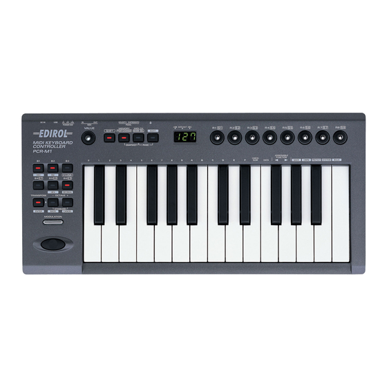
Thank you for purchasing the MIDI keyboard controller PCR-M1.
Before using this unit, carefully read the sections entitled:
"USING THE UNIT SAFELY" and "IMPORTANT NOTES"
(OWNER'S MANUAL p. 2–4). These sections provide
important information concerning the proper operation of
the unit. Additionally, in order to feel assured that you have
gained a good grasp of every feature provided by your new
unit, Owner's manual should be read in its entirety. The
manual should be saved and kept on hand as a convenient
reference.
Copyright © 2004 ROLAND CORPORATION
All rights reserved. No part of this publication may be reproduced in any
form without the written permission of ROLAND CORPORATION.
Advertisement
Table of Contents

Subscribe to Our Youtube Channel
Related Manuals for Edirol PCR-M1


Summary of Contents for Edirol PCR-M1
- Page 1 Owner’s Manual Thank you for purchasing the MIDI keyboard controller PCR-M1. Before using this unit, carefully read the sections entitled: “USING THE UNIT SAFELY” and “IMPORTANT NOTES” (OWNER’S MANUAL p. 2–4). These sections provide important information concerning the proper operation of the unit.
- Page 2 Never place it on stands that could wobble, or on inclined surfaces....................Before using the unit in a foreign country, consult with your retailer, the nearest Roland Service Center, or an authorized Roland distributor, as listed on the “Infor- mation” page.
- Page 3 Immediately turn the power off, remove the AC polarity. adaptor from the outlet, and request servicing by your retailer, the nearest Roland Service Center, or • Avoid using new batteries together with used ones. In an authorized Roland distributor, as listed on the addition, avoid mixing different types of batteries.
-
Page 4: Important Notes
IMPORTANT NOTES In addition to the items listed under “USING THE UNIT SAFELY” on page 2 -3, please read and observe the following: Power Supply: Use of Placement Batteries • This device may interfere with radio and television reception. Do not use this device in the vicinity of such •... -
Page 5: Repairs And Data
However, in certain cases (such as when circuitry related to memory itself is out of order), we regret that it may not be possible to restore the data, and Roland assumes no liability concerning such loss of data. -
Page 6: Table Of Contents
Contents Contents of the package ............10 Quick page reference table ........... 11 Names of things and what they do........12 Panel............................. 12 Rear Panel ........................... 15 Inserting batteries....................... 16 Setup ............. 17 Getting Connected and Installing Drivers (Windows) ..18 Installing the driver ...................... - Page 7 USB connections with your computer – Sending MIDI messages to your application – ............42 USB connections with your computer – Using the PCR-M1 as a MIDI interface –..............43 When using a MIDI connection ..................44 Input / output devices............45 Use MIDI functionality ............
- Page 8 H-COMPATIBLE (ProTools LE, Digital Performer) SET (MEMORY: 9) ......................101 GS SET ......................... 101 XG SET ........................103 Troubleshooting..............104 Problems related to the USB driver................104 Problems when using the PCR-M1 ................110 MIDI implementation............112 Main specifications.............. 117 index..................118...
- Page 9 Memo...
-
Page 10: Contents Of The Package
Contents of the package The PCR-M1 includes the following items. When you open the package, first make sure that all items are included. If any are missing, contact the dealer where you purchased the PCR-M1. ● USB MIDI Keyboard Controller PCR-M1 fig.PCR-M1... -
Page 11: Quick Page Reference Table
USB MIDI Driver Mode p. 93 Startup Memory p. 93 Factory Reset p. 94 MIDI I/F MODE p. 94 VALUE ENCODER p. 95 Trouble Shooting Problems related to the USB driver p. 104 Problems when using the PCR-M1 p. 110... -
Page 12: Names Of Things And What They Do
In addition, operating a controller will cause its current value to appear in the display for a time. Lights if the PCR-M1 is connected to your computer via USB. This will blink when MIDI messages are transmitted via USB or MIDI OUT. - Page 13 Names of things and what they do fig.panel-2 Controllers [R1] – [R8], [S1] ([SHIFT] + [R1]) – [S8] ([SHIFT] + [R8]) You can assign MIDI messages to these controllers. (➝Edit mode (EDIT) (p. 58)) When the [SHIFT] button is unlit (SHIFT OFF), these controllers correspond to [R1]--[R8]. When the button is lit (SHIFT ON), they correspond to [S1]--[S8].
- Page 14 Names of things and what they do fig.panel-3 DEC Button Decreases the value of a setting by one (except in PLAY mode (p. 48)). INC Button Increases the value of a setting by one (except in PLAY mode (p. 48)). V-LINK Button The V-LINK function (p.
-
Page 15: Rear Panel
In this case, the power will be supplied from your computer via the USB cable. To use the PCR-M1 with bus power, set the power switch to USB. * For some computers, the PCR-M1 may not operate if bus power is used. In this case, use the included AC adaptor. -
Page 16: Inserting Batteries
Inserting batteries Make sure that the power switch is turned off. Remove the battery cover located on the rear panel of the PCR-M1. * When turning the unit upside-down, get a bunch of newspapers or magazines, and place them under the four corners or at both ends to prevent damage to the buttons and controls. -
Page 17: Setup
Setup This section explains how to install the drivers needed for connecting the PCR to a computer, and make the necessary settings. Getting Connected and Installing Drivers (Windows) ... (p. 18) Getting Connected and Installing Drivers (Macintosh)..(p. 31) What is a driver? A “driver”... -
Page 18: Getting Connected And Installing Drivers (Windows)
Getting Connected and Installing Drivers (Windows) Installing the driver The installation procedure will differ depending on your system. Please proceed to one of the following sections, depending on the system you use. • Windows XP users ............(p. 18) • Windows 2000 users............(p. 23) •... - Page 19 Getting Connected and Installing Drivers (Windows) Click [OK] to close the System Properties dialog box. If the screen indicates Exit all currently running software (applications). “Windows can perform the same action each Also close any open windows. If you are using virus checking or similar time you insert a disk or software, be sure to exit it as well.
- Page 20 Getting Connected and Installing Drivers (Windows) fig.2-7_20 The screen will indicate “Please choose your search and installation options”. Select “Don’t search. I will choose the driver to install”, and click [Next]. Make sure that the “Model” field indicates “EDIROL PCR”, and click [Next].
- Page 21 Getting Connected and Installing Drivers (Windows) The screen will indicate “Completing the Found New Hardware Wizard”. Make sure that the “Model” field indicates “EDIROL PCR”, Click [Finish]. Wait until “Found New Hardware” appears near the taskbar. When driver installation has been completed, the System Settings Change If the System Settings dialog box will appear.
- Page 22 Getting Connected and Installing Drivers (Windows) ■ Enabling background processing In Windows XP, make settings to enable background processing. If you fail to make this setting, you may experience interruptions in the sound. To ensure that MIDI processing occurs smoothly, use the following procedure to make settings.
-
Page 23: Windows 2000 Users
Getting Connected and Installing Drivers (Windows) Windows 2000 users Disconnect all USB cables except for a USB keyboard and USB mouse (if Log on to Windows as a user with administrative used). privileges (such as Administrator) Open the System Properties dialog box. Click the Windows Start menu, and from the menu that appears, select Settings | Control Panel. - Page 24 Getting Connected and Installing Drivers (Windows) fig.05-5_30 To check the drive name In the Windows desktop, In the dialog box that appears, double-click the My input the following into the Computer icon. In the “Open” field, and click [OK]. window that appears, check the drive name of the CD-ROM drive into (drive name):...
- Page 25 Getting Connected and Installing Drivers (Windows) If the “File signature verification” (Step 4) setting was not set to “Ignore,” a “Digital Signature Not Found” dialog box will appear. If “File signature verification” is set to “Warn” 1. Click [Yes]. 2. Continue the installation. The screen will indicate “Completing the Found New Hardware Wizard”.
- Page 26 Getting Connected and Installing Drivers (Windows) ■ Enabling background processing In Windows 2000, make settings to enable background processing. If you fail to make this setting, you may experience interruptions in the sound. To ensure that MIDI processing occurs smoothly, use the following procedure to make settings.
-
Page 27: Windows Me/98 Users
Getting Connected and Installing Drivers (Windows) Windows Me/98 users With the PCR disconnected, start up Windows. Disconnect all USB cables except for a USB keyboard and USB mouse (if used). If you are using virus checking or similar software, be sure to exit it as well. Exit all currently running software (applications). -
Page 28: Settings And Checking
Getting Connected and Installing Drivers (Windows) Settings and checking ■ Specifying the MIDI input/output destination Windows XP users * These settings are valid only when using the PCR as a MIDI interface. For details on connections, refer to “USB connections with your computer“(p. 43). Open Control Panel. -
Page 29: Windows 2000 / Me Users
Getting Connected and Installing Drivers (Windows) Windows 2000 / Me users * These settings are valid only when using the PCR as a MIDI interface. For details on connections, refer to “USB connections with your computer“(p. 43). Open Control Panel. Click the Windows Start menu, and from the menu that appears, select Settings | Control Panel. -
Page 30: Windows 98 Users
Getting Connected and Installing Drivers (Windows) Windows 98 users * These settings are valid only when using the PCR as a MIDI interface. For details on connections, refer to “USB connections with your computer“(p. 43). Open Control Panel. Click the Windows Start menu, and from the menu that appears, select Settings | Control Panel. -
Page 31: Getting Connected And Installing Drivers (Macintosh)
Getting Connected and Installing Drivers (Macintosh) The installation procedure will differ depending on your system. Please proceed to one of the following sections, depending on the system you use. • Mac OS X users ..............(p. 31) • Mac OS 9 users ..............(p. 34) Mac OS X users ■... -
Page 32: Mac Os Settings
Getting Connected and Installing Drivers (Macintosh) ■ Mac OS settings If you’re using the PCR as a MIDI interface (i.e., connected to an external MIDI device), make settings as described below. For a connection diagram, refer to “USB connections with your computer” (p. 43). Use the USB cable to connect the PCR to your computer. -
Page 33: Software Settings
Getting Connected and Installing Drivers (Macintosh) ■ Software settings Once the connections have been completed, turn on power to your various Use the USB cable to connect the PCR to your computer. devices in the order specified. By turning on 1. -
Page 34: Mac Os 9 Users
Getting Connected and Installing Drivers (Macintosh) Mac OS 9 users ■ Installing the driver Use either OMS or FreeMIDI as the MIDI driver. The included PCR driver is an add-on module for using the PCR with OMS or OMS can be found in the OMS 2.3.8 E folder within FreeMIDI. -
Page 35: Setting The Driver
Getting Connected and Installing Drivers (Macintosh) ■ Setting the driver If you are using FreeMIDI, proceed to FreeMIDI settings (p. 38). Once the connections have been completed, turn on OMS settings power to your various devices in the order specified. By turning on devices in the wrong Use the USB cable to connect the PCR to your computer. - Page 36 Getting Connected and Installing Drivers (Macintosh) fig.3-8_35 Choose “Open” from the File menu. From the OMS Setting folder that you copied in step 3, select the PCR file, and click [Open]. A screen like the one shown here will appear. fig.3-9_35 From the Edit menu, select OMS MIDI Setup.
- Page 37 Getting Connected and Installing Drivers (Macintosh) fig.OMS3 For details on the PCR’s Try moving the fader of the PCR. If input/output devices, refer to Input / output the arrow beside number 2 or 3 in devices (p. 45). the diagram at right blinks, the settings have been made correctly.
-
Page 38: Freemidi Settings
Getting Connected and Installing Drivers (Macintosh) FreeMIDI settings Once the connections have been completed, turn on Use the USB cable to connect the PCR to your computer. power to your various 1. Set the PCR’s power switch to the “OFF” position. devices in the order specified. - Page 39 Getting Connected and Installing Drivers (Macintosh) fig.FreeMIDI_40 Try moving the fader of the PCR. If the number 2 or 3 in the diagram at For details on the PCR’s right changes to a shape, the input/output devices, settings have been made correctly. refer to Input / output If a MIDI sound module is devices (p.
- Page 40 Memo...
-
Page 41: Operation
Operation The PCR-M1 is a controller that transmits MIDI messages. You cannot perform using only the PCR-M1 by itself. You will need to connect it to a sound module or computer. The various controllers ([R1–R8], [S1–S8], [B1–B6], [L1–L3], [P1, P2]) can be assigned almost any message you want to get the control you need for your particular setup. -
Page 42: Basic Connections And Midi Flow
■ MIDI flow Turn MIDI I/F MODE OFF as described in “MIDI I/F MODE” (p. 94). fig.flow-usb MIDI I/F MODE OFF PCR-M1 MIDI OUT DEVICE EDIROL PCR MIDI OUT MIDI OUT EDIROL PCR... -
Page 43: Usb Connections With Your Computer - Using The Pcr-M1 As A Midi Interface
Basic connections and MIDI flow USB connections with your computer – Using the PCR-M1 as a MIDI interface – * If you want to use Media Player to play a sound module connected to the PCR’s MIDI OUT connector, make driver settings as described in “Specifying the MIDI input/output destination”(p. 28). -
Page 44: When Using A Midi Connection
(power blackout or power cord disconnection). Use only the specified expression pedal (EV Series; sold separately). By connecting any other expression pedals, you risk causing malfunction and/or damage to the unit. ■ MIDI flow fig.flow-midi PCR-M1 MIDI OUT BULK RECEPTION MIDI IN PORT 1... -
Page 45: Input / Output Devices
For details on these settings, refer to the owner’s manual for your software. * If you are unable to select the PCR-M1 in the device settings for your software, it is possible that the driver was not installed correctly. Please reinstall the driver. -
Page 46: Two Midi Ports
The output destination of the MIDI messages transmitted when you operate the PCR-M1’s knobs, and buttons can be specified separately for each controller. (Assign MIDI messages (EDIT) (p. 58)) -
Page 47: Use Midi Functionality
You can switch modes at any time, as shown below. Mode Switching modes Explanation Transmit MIDI messages PLAY mode When you turn on the power, the PCR-M1 will by playing the keyboard (p. 48) start up in PLAY mode. or operating the control- lers. -
Page 48: Startup Mode
In order to send MIDI messages from the PCR-M1 to your application, perform the following steps. Set the MIDI channel the PCR-M1 will use to transmit to the same channel on the application is using to receive on. Use MIDI Channel mode to set the MIDI transmit channel. -
Page 49: Features Useful When Playing
Octave Shift and Transpose can be set independently. To switch the PCR-M1 to PLAY mode... When you turn on the power, the PCR-M1 will start up in PLAY mode. To return to PLAY mode from another mode (➝Setting the MIDI Transmit Channel (p. 50)), press the button of the current mode (i.e., the button that is lit). -
Page 50: Setting The Midi Transmit Channel
Use MIDI functionality Setting the MIDI Transmit Channel To control your sound module, set the PCR-M1’s current channel to the MIDI receive channel that’s selected on your sound module. Use MIDI Channel mode to set the current channel. Current channel The “current channel”... - Page 51 If you are not in Play mode, you can use one of two ways to input a numerical value into the PCR-M1; Decimal input mode or Hexadecimal input mode. If you want to input decimal numbers, press the [DECIMAL] button. If you want to input hexadecimal numbers, press the [HEX] button.
-
Page 52: Selecting Sounds On A Sound Module (Sending Program Change / Bank Select Massages)
Use MIDI functionality Selecting Sounds on a Sound Module (Sending Program Change / Bank Select Massages) To select a sound on your MIDI sound module, transmit a Program Change in Program Change mode. To select a sound from a different bank, first use Bank mode to transmit a Bank Select message that switches the bank. -
Page 53: Program Change Mode (Program Change)
Use MIDI functionality ■ Program Change Mode (PROGRAM CHANGE) This mode lets you transmit a program change message on the current channel (p. 50). fig.PC-1_90 fig.program Press the [SHIFT] button so it is lit. Press the [PGM CHANGE] button. The [PGM CHANGE] button will light. The display will indicate the program change that was transmitted most recently. -
Page 54: Bank Mode (Bank)
Use MIDI functionality ■ Bank mode (BANK) This mode lets you transmit a bank select (MSB, LSB) message on the current channel. The program change message you most recently transmitted (specified) in Program Change mode (p. 53) will also be transmitted following the bank select message. fig.BANK2_90 fig.bank Press the [SHIFT] button so it is lit. -
Page 55: Transmitting A Reset Message
Use MIDI functionality Transmitting a Reset message (What to do if there are “stuck” MIDI notes) If notes on a connected MIDI sound module become “stuck”, or if there is something wrong with the sound, you can execute the Panic function to solve the problem. When you execute the Panic function, All sound off, All notes off, and Reset all controllers messages will be transmitted on all channels. -
Page 56: Changing The Memory Sets
(EDIT) (p. 58). If you edit the controller settings of a memory you recall, and want to keep your changes, you must save the memory before powering down the PCR-M1. For the procedure, refer to Saving a memory set (SAVE) (p. 86). -
Page 57: Transmitting The Current Controller Values All At Once (Snapshot)
Use MIDI functionality Transmitting the current controller values all at once (SNAPSHOT) Once you have set the various controllers to the desired settings, you can transmit a detailed description of this state in the form of a “snapshot”. When you execute this function, the current values of the controllers [R1–R8] or [S1–S8] will be transmitted. -
Page 58: Assign Midi Messages (Edit)
Use MIDI functionality Assign MIDI messages (EDIT) You can assign the following functions to a controller. You will use Edit mode to assign MIDI messages. NOTE NOTE ASSIGN (p. 60) You can copy assigned messages to AFTERTOUCH AFTERTOUCH ASSIGN (p. 62) another controller, or cancel an as- CONTROL CHANGE CONTROL CHANGE ASSIGN (p. - Page 59 Use MIDI functionality Specifying the button mode When you make Assign settings (p. 58) in Edit mode to assign a message to a button, you must specify the operating mode of the button (button mode). When you use a button as a controller, turning the button on will transmit the maximum specified value, and turning it off will transmit the minimum value.
-
Page 60: Note Assign
Use MIDI functionality NOTE ASSIGN Here’s how to assign a Note message to a controller. In addition to being used to play sounds, note messages can also be used to control a sequencer. Mode Keyboard Velocity Port Basic mode 100 (64H) PORT 1 Advanced mode Assignable... -
Page 61: Advanced Mode
Use MIDI functionality ● Advanced mode 1 Advanced mode 1 of NOTE ASSIGN lets you specify the velocity value in addition to the items of Basic mode. 1. Press the [EDIT] button. 2. Slightly move the controller to which you want to assign a Note message. In the case of a button, press that button. -
Page 62: Aftertouch Assign
Use MIDI functionality AFTERTOUCH ASSIGN Here’s how to assign an Aftertouch message to a controller. Mode Keyboard Message Value range Port Basic mode Channel Pressure 0-127 (00–7FH) Port 1 Advanced mode 1 Channel Pressure Upper and Assignable lower limits are assignable Advanced mode 2 Polyphonic Key Pressure 0-127 (00–7FH) - Page 63 Use MIDI functionality ● Advanced mode 1–3 Advanced mode 1 of AFTERTOUCH ASSIGN lets you specify the upper and lower limits of the aftertouch value in addition to the items of Basic mode. Advanced modes 2 and 3 let you specify an aftertouch message for an individual note (Polyphonic Key Pressure) instead of specifying the channel.
- Page 64 Use MIDI functionality Specifying the range of values (upper and lower limits) If in Edit mode you selected an Assign type (p. 58) that lets you specify the range of values, you will need to specify the upper limit and lower limit of the value. * Normally, when using Decimal input mode, the value you are specifying appears in the display as a three digit number.
-
Page 65: Control Change Assign
Use MIDI functionality CONTROL CHANGE ASSIGN Here’s how to assign a control change message to a controller. Mode keyboard Value range Port Basic mode 00–7FH PORT 1 Advanced mode 1 Upper and lower limits are Assignable assignable Advanced mode 2 Simulates a rotary encoder Assignable ●... - Page 66 Use MIDI functionality ● Advanced mode 1 Advanced mode 1 of CONTROL CHANGE ASSIGN lets you specify the upper and lower limits of the control change value in addition to the items of Basic mode. 1. Press the [EDIT] button. 2.
- Page 67 Use MIDI functionality ● Advanced mode 2 Advanced mode 2 simulates the operation of a conventional rotary encoder. If this is assigned to a controller, moving that controller toward the right (upward) of center will have the same effect as turning the encoder clockwise, and moving the controller toward the left (downward) of center will have the same effect as turning the encoder counterclockwise.
-
Page 68: Program Change Assign
Use MIDI functionality PROGRAM CHANGE ASSIGN Here’s how to assign a program change message to a controller. Mode Number Effect Bank Port Basic mode Fixed value Not output PORT 1 Advanced mode 1 Upper and lower limits are Not output PORT 1 assignable Advanced mode 2... - Page 69 Use MIDI functionality ● Advance mode 1, 2 Advanced mode 1 of PROGRAM CHANGE ASSIGN lets you specify the upper and lower limits of the program change value. Advanced mode 2 lets you transmit BANK LSB/MSB settings in addition to the program change. 1.
- Page 70 Use MIDI functionality ● Advanced modes 3 and 4 Advanced mode 3 lets you assign the Program Change Decrement function (PC DEC) to a controller. Advanced mode 4 lets you assign the Program Change Increment function (PC INC) to a controller.
-
Page 71: Rpn / Nrpn Assign
Use MIDI functionality RPN / NRPN ASSIGN Here’s how you can assign an RPN or NRPN message to a controller. Data entry MSB Data entry LSB Mode Keyboard Port (CC#6) range (CC#38) range Basic mode 0-127 (00–7FH) Not transmitted PORT 1 Advanced mode 1 Upper and lower limits 0-127 (00–7FH) - Page 72 Use MIDI functionality Press the [ENTER] button. fig.BANK-3 Use the [VALUE] dial, the [DEC] [INC] buttons, or the [0] - [F] keys to specify the RPN LSB (CC#100) or NRPN LSB (CC#98). *1 Reference Press the [ENTER] button. If you are making an assignment for a button, specify the button mode. (➝Specifying the button mode (p.
- Page 73 Use MIDI functionality ● Advanced mode In Advanced mode for RPN/NRPN, you can specify the upper and lower limit of the data entry MSB (CC#06) value when the RPN/NRPN message is transmitted, as well as the various settings available in Basic mode. 1.
-
Page 74: Sys Ex. Assign
Use MIDI functionality Sys Ex. ASSIGN Here’s how you can assign a system exclusive message to a controller. Advanced mode 2 lets you assign a single-byte system message (System realtime message, tune request). Advanced modes 3 and 4 let you assign any desired message. (Input up to 24 bytes) Key- Mode Mode... - Page 75 11. Input the second and subsequent bytes in the same way. 12. After you have input the number of bytes you specified in step 7, the PCR-M1 will check whether the messages you’ve input are indeed valid MIDI messages. If there is a problem, the display will indicate “ERR”.
-
Page 76: Sys Ex. Assign Items
• Inputting channel/block data (p. 78) ■ Specifying the checksum The PCR-M1 can automatically calculate the checksum of a system exclusive message and embed it in the message. In order to use this function, you must use the following procedure to specify the starting location from which the checksum is calculated, and the location at which the checksum is inserted. - Page 77 Use MIDI functionality ■ Specifying the location of the data Here’s how to specify the location and data type of the variable portion (data) within a system exclusive message. The range of data values will be the default range in the case of Basic mode or Advanced mode 3.
- Page 78 (The block number is not actually a channel, but corresponds to the “part” within a GS sound module. On the PCR-M1, this corresponds to the channel for the sake of convenience.) Current channel For an actual example, refer to Bend Pitch Control (p.
-
Page 79: Examples Of Assigning System Exclusive Messages
Use MIDI functionality Examples of assigning system exclusive messages • GM2 System On (p. 79) • Master Volume (p. 80) • Bend Pitch Control (p. 81) ● GM2 System On F0 7E 7F 09 03 F7 Here’s how to assign a GM2 System On system exclusive message in Basic mode. 1. -
Page 80: Master Volume
Use MIDI functionality ● Master Volume F0 7F 7F 04 01 vL vM F7 Since a Master Volume message has a data range of 00 00–7F 7F and we do not need to specify the range, we will use Basic mode. Since the two bytes of data are in the order of LSB and then MSB, we will select “DT3”... - Page 81 Use MIDI functionality ● Bend Pitch Control Since the GS Bend Pitch Control message has a data range of 40H–58H (0–24 semitones), we will select Advanced mode 1, which lets us specify the range. Since the data format is one byte, we will select “DT0”...
- Page 82 Use MIDI functionality 18. Since the ten byte will contain the checksum, press the [CHECKSUM] key to specify the location at which the checksum will be input. The display will blink “CS1” (Checksum Type 1). 19. Confirm what’s indicated and press [ENTER]. 20.
-
Page 83: Tempo Assign
Use MIDI functionality TEMPO ASSIGN You can assign a controller to adjust the speed (20–250) of the F8 Clock message. * In order to transmit F8 Clock messages, the F8 CLOCK setting must be “ON”. (➝“F8 CLOCK ON/OFF” (p. 92)) fig.edt2 Press the [EDIT] button. -
Page 84: Copying A Midi Message Assignment (Assign Copy)
Use MIDI functionality Copying a MIDI message assignment (ASSIGN COPY) Here’s how a message assigned to a controller can be copied to another controller. fig.edt2 Press the [EDIT] button. The display will indicate “EDT”. fig.r-1 Slightly move the controller to which you want to copy the assignment (the “copy destination”). -
Page 85: Canceling A Midi Message Assignment (No Assign)
Use MIDI functionality Canceling a MIDI message assignment (NO ASSIGN) Here’s how you can cancel the message assigned to a controller. Once its assignment is cancelled, no message will be transmitted when you operate that particular controller. fig.edt2 Press the [EDIT] button. The display will indicate “EDT”. -
Page 86: Saving A Memory Set (Save)
Use MIDI functionality Saving a memory set (SAVE) Here’s how to save the settings of the current memory into internal memory. You can save settings into internal memory numbers 1–F. You cannot save to memory number 0 (GM2). * After you edit the settings, perform the “SAVE” operation as needed. If you turn off the power without performing “SAVE”, your changes will be lost. -
Page 87: Transmitting/Receiving Bulk Data (Bulk)
1–F will not be affected. ALL BULK The received data will overwrite memories 1–F. fig.rs1 Confirm what’s indicated and press the [ENTER] button. The third digit of the display will blink, and the PCR-M1 will wait to receive bulk data. - Page 88 Use MIDI functionality About the display in Bulk mode fig.bulk-dis Waiting to receive Receive SINGLE (blinking) BULK 1st digit: indicates Receive mode or 3rd digit: indicates Transmit mode Transmit Waiting to transmit Transmitting/Receiving/Waiting states BULK (blinking) receiving Transmitting 2nd digit: Single Bulk or All Bulk transmitting Transmit bulk data from your sequencer or other device.
- Page 89 Confirm what’s indicated and press the [ENTER] button. fig.ts-1 The third digit of the display will blink, and the PCR-M1 will wait to transmit bulk data. Press the [ENTER] button. On your sequencer software, specify “PCR -1 2” as the MIDI input device. For details on this setting, refer to the manual of your sequencer software.
-
Page 90: Protecting A Memory Set (Protect)
Use MIDI functionality Protecting a memory set (PROTECT) If you turn the Protect setting ON, ALL BULK (p. 87) reception and SAVE (p. 86) operations will be disabled. fig.edt2 Press the [EDIT] button. The display will indicate “EDT”. fig.ptc Press the [PROTECT] key. The display will blink “PTC”. -
Page 91: System Settings
System settings Here’s how you can make various system settings for the PCR-M1. fig.edt2 Press the [EDIT] button. The display will indicate “EDT”. fig.sy0 Press the [SYSTEM] key. The display will indicate “SY0”. Use the [0] - [9], [A] keys to specify the System setting that you want to set, and then press the [ENTER] button. -
Page 92: F8 Clock On / Off (Keyboard: 0)
System settings F8 CLOCK ON / OFF (Keyboard: 0) Perform steps 1-3. fig.hyo 4. Use the [VALUE] dial, the [DEC] [INC] buttons or the [0] or [1] keys to switch F8 CLOCK ON / OFF. The display will indicate either “ON” or “OFF”. 5. -
Page 93: Keyboard Port Set (Keyboard: 4)
GM2 MEMORY be loaded into current memory (p. 86) regardless of the state in which the power was turned off. Upon power-up, the PCR-M1 will recall the memory LAST ACCESS that was last recalled or saved into current memory (p. -
Page 94: Factory Reset (Keyboard: 8)
The MIDI connectors on the rear panel of the PCR-M1 will function as a MIDI interface. MIDI messages from a com- puter connected via USB to the PCR-M1 will be sent to the MIDI sound module connected to the PCR-M1’s MIDI OUT connector. -
Page 95: Value Encoder (Keyboard: A)
Assigns the KEY VELOCITY parameter to the VALUE en- coder. In KEY VELOCITY MODE, the velocity value is fixed. The PCR-M1 transmits velocity values that correspond to the force with which you play the keyboard, but if KEY VELOCITY is assigned to the VALUE encoder, the fixed... -
Page 96: V-Link Mode
When the [SHIFT] button is lit (SHIFT ON), pressing the [V-LINK] button (B3) will make the PCR-M1 transmit a V-LINK ON message and enter V-LINK mode. When you press the [V-LINK] button once again, the PCR will transmit a V-LINK OFF message and will exit V-LINK mode. -
Page 97: Appendices
Appendices This section contains troubleshooting information and explanations of convenient functions.You may read this material as necessary. Memory sets ..................p. 98 Troubleshooting................p. 104 MIDI implementation ..............p. 112 Main specifications..............p. 117... -
Page 98: Memory Sets
Memory sets With the factory settings, the GM2 set is assigned to the controllers. Use the included template. The following memory sets are also provided. GM2 set (MEMORY: 0)........(p. 98) H-COMPATIBLE (ProTools LE, Digital Performer) SET MCR-8 MODE 3 (SONAR) SET ....... (p. 99) (MEMORY: 9)............ -
Page 99: ■ Mcr-8 Mode 3 (Sonar) Set
Memory sets ■ MCR-8 MODE 3 (SONAR) SET When using this memory set, turn the PCR-M1’s OMNI (p. 51) setting OFF. MCR-8 MODE 3 (SONAR) - A (MEMORY: 1) MCR-8 MODE 3 (SONAR) - B (MEMORY: 2) Message Message Parameter Range (Hex.) -
Page 100: ■ Mcr-8 Mode 4 (Cubase 5/Sx) Set
Memory sets ■ MCR-8 MODE 4 (Cubase 5/SX) SET When using this memory set, turn the PCR-M1’s OMNI (p. 51) setting OFF. MCR-8 MODE 4 (Cubase 5/SX) - A (MEMORY: 5) MCR-8 MODE 4 (Cubase 5/SX) - B (MEMORY: 6) -
Page 101: H-Compatible (Protools Le, Digital Performer) Set (Memory: 9)
0(00) / 127(7F) EXPRESSION CC 11(0B) 0(00) - 127(7F) ■ GS SET When using this memory set, you will find it convenient to turn the PCR-M1’s OMNI (p. 51) setting ON. GS-A (MEMORY: A) Parameter Message (Hex.) Range (Hex.) Port... - Page 102 Memory sets GS-B (MEMORY: B) Parameter Message (Hex.) Range (Hex.) Port CHORUS MACRO F0 41 10 42 12 40 01 38 dd SUM F7 0(00) - 7(07) CHORUS PRE-LPF F0 41 10 42 12 40 01 39 dd SUM F7 0(00) - 7(07) CHORUS DELAY F0 41 10 42 12 40 01 3C dd SUM F7...
-
Page 103: Xg Set
Memory sets ■ XG SET When using this memory set, you will find it convenient to turn the PCR-M1’s OMNI (p. 51) setting ON. XG-A (MEMORY: D) Parameter Message (Hex.) Range (Hex.) Port BEND PITCH CONTROL F0 43 10 4C 08 0ch 23 dd F7... -
Page 104: Troubleshooting
• Is the PCR-M1 connected correctly? Make sure that the USB connector of your computer is connected to the PCR-M1 by a USB cable. • Is the CD-ROM correctly inserted into your CD-ROM drive? Installation is not possible unless the CD-ROM included with the PCR-M1 is inserted in your CD- ROM drive. - Page 105 Then set the PCR to the following driver mode, turn the PCR’s power on again, and install the driver once again.] “USB MIDI DRIVER MODE “(p. 93) 0: Original driver Is OMS or FreeMIDI installed? (Mac OS 9) The PCR-M1 driver cannot be installed unless OMS or FreeMIDI are installed. Please install OMS or FreeMIDI.
- Page 106 In this case, you may be able to solve the problem by connecting a USB hub. If the above actions do not solve the problem, it is possible that the PCR-M1 has been incorrectly detected by the computer. Please reinstall the driver from the beginning of the procedure. (Getting Connected and Installing Drivers (Windows) (p.
- Page 107 “Found unknown device” appears even though you installed the driver If your computer or USB hub has two or more USB connectors, and you connect the PCR-M1 to a USB connector to which the PCR-M1 has never been connected before, the “Unknown device”...
- Page 108 Macintosh, and then restart it. In some cases, the PCR-M1 will not be detected if you have connected it to the USB connector located on the keyboard of the Macintosh. Please connect it to a USB connector on the Macintosh...
-
Page 109: Deleting The Driver
Troubleshooting ■ Deleting the driver If you were unable to install the driver according to the procedure given, the PCR-M1 may not be recognized correctly by the computer. In this case, use the following procedure to delete the driver, and then follow the procedure to install the driver once again. -
Page 110: Problems When Using The Pcr-M1
For details on making this setting, refer to the owner’s manual of the software you are using. • Was the driver installed correctly? In order for you to play back audio data via the PCR-M1, the driver must be installed. For installation and settings, refer to “Getting Connected and Installing Drivers” (Windows:p. 18/ Macintosh: p. 31). - Page 111 Troubleshooting...
-
Page 112: Midi Implementation
3rd byte ●Data transmission n = MIDI channel number: 0H – FH (Ch.1 – 16) The PCR-M1 can use Bulk Dump (p. 114) to transfer its internal Memory sets (p. kk = note number: 00H – 7FH (0 – 127) 98). -
Page 113: Program Change
MIDI implementation ●Program change ■System common message Status 2nd byte On the PCR-M1 you can assign the following system common messages to any controller and transmit them. ●MTC quarter frame n = MIDI channel number: 0H – FH (Ch.1 – 16) pp = Program number: 00H –... -
Page 114: System Exclusive Message
For example, this can be used to store all settings of a device into a computer or 10H,00H,00H,00H,70H sequencer. On the PCR-M1, a bulk dump will be transmitted when you execute the Bulk mode Byte Explanation operation BULK TX. The bulk dump is transmitted as several exclusive messages. -
Page 115: Supplementary Material
05. ●Checksum calculation In order to verify that the message was received correctly, Roland exclusive messages (RQ1, DT1) add a checksum following the end of the data (before the F7). The checksum value is determined by the address and data (or size) of the exclusive message that is transmitted. - Page 116 MIDI implementation fig.midi-chart.e MIDI KEYBOARD CONTROLLER Date : Sep. 01, 2004 MIDI Implementation Chart Version : 1.00 Model PCR-M1 Transmitted Recognized Function... Remarks Basic Default Channel Changed 1–16 Default Mode 3 Mode Messages OMNI ON/OFF, MONO, POLY Altered ************** Note 0–127...
-
Page 117: Main Specifications
Main specifications ■ PCR-M1: MIDI Keyboard Controller ● Keyboard ● Accessories 25 Keys (S.L.I.M with velocity) CD-ROM USB Cable * S.L.I.M = Short-stroke, Low-profile Impact Mechanism Pedal Adaptor Cable x 2 ● Display Owner's Manual 7 segments, 3 characters (LED) -
Page 118: Index
index CONTROL CHANGE ....58, 65–66, 112 CONTROL CHANGE ASSIGN ....58, 66 AC adaptor jack ..........15 Controllers ............ 13–15 Active sensing ..........113 COPY ..............84 Advanced mode ..........58 CTRL IN port ............. 46 Aftertouch Cubase ............... 100 Aftertouch Assign ...... - Page 119 index MIDI CH / BANK SEL Button ......12 MIDI Channel mode ......... 47 Generic driver ............ 93 MIDI Devices ............. 45 GM2 MEMORY ..........93 MIDI flow ............44 GM2 set ............... 98 MIDI IN/OUT connectors ....... 15 GM2 System On ..........79 MIDI interface ............
- Page 120 index Pitch Bend ............49 System common message ......113 Pitch bend change ..........113 system exclusive message ..74, 77–79, 112, 114 PLAY mode ............47 system message ..........74 Polyphonic Key Pressure ....62–63, 112 System realtime message ....... 113 port ............
- Page 121 Memo...
- Page 122 For EU Countries...
-
Page 123: Declaration Of Conformity
For the USA DECLARATION OF CONFORMITY Compliance Information Statement Model Name : PCR-M1 Type of Equipment : MIDI KEYBOARD CONTROLLER Responsible Party : Roland Corporation U.S. Address : 5100 S. Eastern AvenueLos Angeles, CA 90040-2938 Telephone : (323) 890 3700... - Page 124 Information When you need repair service, call your nearest EDIROL/Roland Service Center or authorized EDIROL/Roland distributor in your country as shown below. IRELAND HONG KONG BRAZIL TRINIDAD MIDDLE EAST Roland Ireland Roland Brasil Ltda. Parsons Music Ltd. AMR Ltd G2 Calmount Park, Calmount...
Need help?
Do you have a question about the PCR-M1 and is the answer not in the manual?
Questions and answers