Table of Contents
Advertisement
Quick Links
Advertisement
Table of Contents

Related Manuals for ThinkPad T60


Summary of Contents for ThinkPad T60
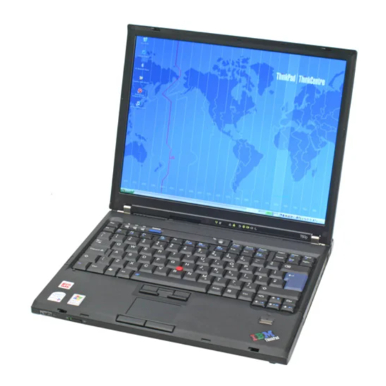
- Page 1 ® ThinkPad T60 and T60p (14.1-inch and 15.0-inch) Hardware Maintenance Manual...
-
Page 2: 1010 Battery Pack
2 , remove the battery pack in the direction shown by arrow When installing: Install the battery pack along the slide rails of the slot. Then make sure that the battery release lever is in the locked position as in this figure. ThinkPad T60 and T60p (14.1-inch and 15.0-inch) -
Page 3: 1020 Ultrabay Slim Device
Removing and replacing a FRU 1020 Ultrabay Slim device Note Ultrabay Slim does not accept any of the following devices: v Ultrabay Plus devices v Ultrabay 2000 devices When you release the switch in step 1 , the lever pops out. In step 2 , pull the lever a little to release the device from the bay. -
Page 4: 1040 Palm Rest Or Palm Rest With Fingerprint Reader
Step Icon Screw (quantity) Color Torque M2 × 14 mm, flat-head, nylon-coated Black 0.167 Nm (1.7 kgfcm) (continued) ThinkPad T60 and T60p (14.1-inch and 15.0-inch) -
Page 5: Removing And Replacing A Fru
Removing and replacing a FRU MT 1951, 1952, 1953, 1954, 1955, 1956, 2007, 2008, 2009, 2613, 2623, and 2637... - Page 6 1. Attach the fingerprint reader connector firmly to the system board. 2. 14.1-in. LCD models: a. Align the front side of the palm rest and the frame first; then place the palm rest as shown in this figure. (continued) ThinkPad T60 and T60p (14.1-inch and 15.0-inch)
- Page 7 Removing and replacing a FRU Note: Make sure that the frame and the front side of the palm rest are attached firmly. (continued) MT 1951, 1952, 1953, 1954, 1955, 1956, 2007, 2008, 2009, 2613, 2623, and 2637...
- Page 8 Removing and replacing a FRU b. Push the palm rest a little toward the keyboard 1 , and press the left-top edge 2 and the right-top edge 3 of the palm rest until they latch. ThinkPad T60 and T60p (14.1-inch and 15.0-inch)
- Page 9 Removing and replacing a FRU 15.0-in. LCD models: a. Align the front side of the palm rest and the frame, and attach the front-center of the palm rest, as shown in this figure. b. Press the left-top edge of the palm rest to latch it, and make sure that the left-top edge, the right-top edge, and the front side of the palm rest are attached firmly.
- Page 10 Removing and replacing a FRU 3. Close the LCD cover and turn the computer over. Then fasten the four screws in the order shown in this figure. ThinkPad T60 and T60p (14.1-inch and 15.0-inch)
- Page 11 Color Torque M2 × 14 mm, flat-head, nylon-coated Black 0.167 Nm (1.7 kgfcm) Lift the keyboard a little in the direction shown by arrow 2 , and then detach the connector 3 . ThinkPad T60 and T60p (14.1-inch and 15.0-inch)
- Page 12 Removing and replacing a FRU When installing: Make sure that the keyboard edges a are under the frame as shown in this figure. MT 1951, 1952, 1953, 1954, 1955, 1956, 2007, 2008, 2009, 2613, 2623, and 2637...
-
Page 13: 1120 Keyboard Bezel And Wireless Wan Antenna Cable (Aux)
Removing and replacing a FRU 1120 Keyboard bezel and wireless WAN antenna cable (AUX) Important For the compatibility of the keyboard bezel, see “FRU compatibility matrix” on page 61. For access, remove these FRUs in order: v “1010 Battery pack” on page 63 v “1040 Palm rest or palm rest with fingerprint reader”... - Page 14 In step 6 , detach the claws. Then remove the keyboard bezel in the direction shown by arrow 7 . When installing: Make sure that all the claws are attached firmly. Then fasten the screws to secure the keyboard bezel. (continued) ThinkPad T60 and T60p (14.1-inch and 15.0-inch)
- Page 15 Removing and replacing a FRU Note: Steps 8 and 9 are for the wireless WAN antenna cable (AUX). When installing: Make sure that the antenna cable is routed along the cable guides. MT 1951, 1952, 1953, 1954, 1955, 1956, 2007, 2008, 2009, 2613, 2623, and 2637...
-
Page 16: 1130 Fan Assembly
“1120 Keyboard bezel and wireless WAN antenna cable (AUX)” on page 86 Step Screw (quantity) Color Torque M2 × 9.5 mm, flat-head, nylon-coated (1) Black 0.167 Nm (1.7 kgfcm) M2 × 3 mm, small-head, nylon-coated (1) Silver 0.167 Nm (1.7 kgfcm) (continued) ThinkPad T60 and T60p (14.1-inch and 15.0-inch) - Page 17 Removing and replacing a FRU Step Screw (quantity) Color Torque M2 × 9.5 mm, flat-head, nylon-coated (3) Black 0.167 Nm (1.7 kgfcm) Attention: Do not handle the fan roughly. Improper handling of the fan can cause distortion or deformation and imperfect contact with components. MT 1951, 1952, 1953, 1954, 1955, 1956, 2007, 2008, 2009, 2613, 2623, and 2637...
- Page 18 Make sure that the fan connector is attached firmly. v When attaching the fan assembly to the frame, take care not to damage the heat sink ( b ) of the fan assembly. (continued) ThinkPad T60 and T60p (14.1-inch and 15.0-inch)
- Page 19 Removing and replacing a FRU v Attach the fan bracket. v Secure the screws in order as shown in this figure. Attention: Do not use an electric screwdriver to secure these screws. MT 1951, 1952, 1953, 1954, 1955, 1956, 2007, 2008, 2009, 2613, 2623, and 2637...
Need help?
Do you have a question about the T60 and is the answer not in the manual?
Questions and answers