
Subscribe to Our Youtube Channel
Related Manuals for Eaton 1000H(XL)


Summary of Contents for Eaton 1000H(XL)
-
Page 1: User Manual
USER MANUAL ON LINE UPS 1000H(XL)/2000H(XL)/3000H(XL)/6000H(XL)/10000H(XL) Uninterruptible Power Supply --24--... -
Page 2: Table Of Contents
Contents 1. Safety and EMC Instructions ......................1-3 1.1 Installation............................1 1.2 Operation ............................2 1.3 Maintenance, Servicing and Faults....................2 1.4 Transport ............................3 1.5 Storage ............................3 1.6 Standards ............................3 2. Description of Commonly Used Symbols ................... 4 3. - Page 3 14. Trouble Shooting ..........................27 15. Operating Mode for all Models ....................28-29 16. Communication Port ......................... 30 17. Software for all models……………………………………………………………………………………. .31 18. Appendix ............................32-36 Appendix1-Display Panel(for 6000H(XL)/10000H(XL)) ..............32 Appendix2-The Corresponding Form of the LED Display for 6000H(XL)/10000H(XL) ....33 Appendix3-Back Panel .........................34-36...
-
Page 4: Safety And Emc Instructions
Voltage level Code 220/230/240V 110/115/120V The description followed in this text is make example with Eaton 1000H(XL)/2000H(XL)/3000H(XL)/6000H(XL)/10000H(XL). 1.1 Installation ★ Condensation may occur if the UPS is moved directly from a cold to a warm environment. The UPS must be absolutely dry before being installed. Please allow an acclimatization time of at least two hours. -
Page 5: Operation
◇ For 6000H / 10000H ★ UPS has provided earthed terminal, in the final installed system configuration, equipotential earth bonding to the external UPS battery cabinets. ★ An integral single emergency switching device which prevents further supply to the load by the UPS in any mode of operation should be provided in the building wiring installation. -
Page 6: Transport
Hazardous voltages may occur between the battery terminals and the ground. Verify that no voltage is present before servicing! ★ Batteries have a high short-circuit current and pose a risk of shock. Take all precautionary measures specified below and any other measures necessary when working with batteries: -... -
Page 7: Description Of Commonly Used Symbols
◇ For 6000H(XL) / 10000H(XL) * Safety IEC/EN 62040-1-1 * EMI Conducted Emission.........:IEC/EN 50091-2 Current>25A Radiated Emission........:IEC/EN 50091-2 Current>25A * EMS ESD............:IEC/EN 61000-4-2 Level 4 RS............:IEC/EN 61000-4-3 Level 3 EFT............:IEC/EN 61000-4-4 Level 4 SURGE..........:IEC/EN 61000-4-5 Level 4 Low Frequency Signals......:IEC/EN 61000-2-2 Warning: This is a product for restricted sales distribution to informed partners. -
Page 8: Introduction 1000H(Xl)/2000H(Xl)/3000H(Xl)
3. Introduction – 1000H(XL)/2000H(XL)/3000H(XL) This On-Line-Series is an uninterruptible power supply incorporating double-converter technology. It provides perfect protection specifically for Novell, Windows NT and UNIX servers. The double-converter principle eliminates all mains power disturbances. A rectifier converts the alternating current from the socket outlet to direct current. This direct current charges the batteries and powers the inverter. -
Page 9: System Description
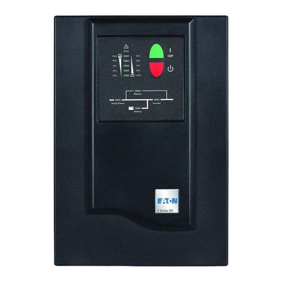
4. System Description Figure 1: Display Panel Switch Function Turn on UPS system: By pressing the ON-Switch “I” the UPS system is turned on. ON - Switch Deactivate acoustic alarm: By pressing this switch an acoustic alarm can be deactivated. When mains power is normal, the UPS system switches to Standby mode by pressing OFF-Switch “... -
Page 10: Connection And Operation
5. Connection and Operation The system may be installed and wired only by qualified electricians in accordance with applicable safety regulations! 5.1 Connection and operation for 1000H(XL)/ 2000H(XL)/ 3000H(XL) When installing the electrical wiring, please note the nominal amperage of your incoming feeder 1) Inspection: Inspect the packaging carton and its contents for damage. - Page 11 5. Connection and Operation Figure 2: Connection diagram of 2000HXL(CE) and 3000H(XL) 2.3) Computer Connection: Connect your computer to the outlet sockets of the UPS system following the above diagram. Caution! *Do not connect equipment which would overload the UPS system (e.g. laser printers) 3) Battery Charge: Fully charge the batteries of the UPS system by leaving the UPS system connected to the mains for 1-2 hours.
- Page 12 5. Connection and Operation 6) Turn Off the UPS: 6.1) In Inverter Mode: Press “ “ button continuously for more than 1 second to turn off the UPS. Then the UPS will get into self-test status first. After having finished the self-test, the UPS will get into bypass mode and the Utility Power LED and Bypass LED will light up.
- Page 13 5. Connection and Operation (6) The "+" terminal of the battery. The black wire is connected to the "-" terminal of the battery. (Note: the green/yellow wire is grounded for protection purpose.) (7) Do not connect the UPS to any load yet. Then, connect the power cord of the UPS to supply utility power to the UPS to make the UPS operation in utility power mode.
-
Page 14: Trouble Shooting
6. Trouble Shooting If the UPS system does not operate correctly, please attempt to solve the problem using the table below. Problem Possible cause Remedy No indication, no warning tone even No input voltage Check building wiring socket outlet and input though system is connected to cable. -
Page 15: Maintenance
7. Maintenance 7.1 Operation The UPS system contains no user-serviceable parts. If the battery service life (3 - 5 years at 25°C ambient temperature) has been exceeded, the batteries must be replaced. In this case please contact your dealer. 7.2 Storage If the batteries are stored in temperate climatic zones, they should be charged every three months for 1-2 hours. -
Page 16: Technical Data
8. Technical Data 8.1 Electrical specifications INPUT Model No. 1000H(XL) 2000H 2000HXL 3000H(XL) Phase Single Frequency (46~54)Hz Current(A) OUTPUT 1000H(XL) 2000H(XL) 3000H(XL) Model No. Power rating 1kVA/0.7kW 2kVA/1.4kW 3kVA/2.1kW Voltage 220/230/240×(1 士 2%)VAC Frequency 50Hz±0.2Hz (Battery mode) Wave form sinusoidal BATTERIES Model No. -
Page 17: Dimensions And Weights
8. Technical Data 8.4 Dimensions and weights Model No. Dimensions W x D x H (mm) Net Weight (kg) 1000H 145X400X220 1000HXL 145X400X220 2000H 192X460X340 34.5 2000HXL 192X460X340 3000H 192X460X340 35.5 3000HXL 192X460X340 14... -
Page 18: Introduction 6000H(Xl)/10000H(Xl)
9. Introduction – 6000H(XL)/ 10000H(XL) 9.1 Product Specification and Performance 1) General Specification Model 6000H 6000HXL 10000H 10000HXL Power Rating 6KVA/4.2KW 6KVA/4.2KW 10KVA/7KW 10KVA/7KW Frequency (Hz) Voltage (176-276)VAC (176-276)VAC (176-276)VAC (176-276)VAC Input Current 31A max. 31A max. 50A max 50A max. Voltage 240VDC 240VDC... -
Page 19: Installation
10. Installation 10.1 Unpacking and Inspection 1) Unpack the packaging and check the package contents. The shipping package contains: A UPS A user manual A communication cable A battery cable (for 6000HXL/10000HXL only) 2) Inspect the appearance of the UPS to see if there is any damage during transportation. - Page 20 10. Installation Note: Do not use the wall receptacle as the input power source for the UPS, as its rated current is less than the UPS’s maximum input current. Otherwise the receptacle may be burned and destroyed. Connect the input and output wires to the corresponding input and output terminals according to the following diagram.
-
Page 21: Operating Procedure For Connecting The Long Backup Time Model Ups With The External Battery
10. Installation Important notes: If the UPS is used in single mode, JPI and JP2 must be connected by 10AWG(6mm2). If the UPS is used in parallel mode, the Jumper between JP1 and JP2 must be removed. 10.3 Operating procedure for connecting the long backup time model UPS with the external battery 1. -
Page 22: Parallel Operation
10. Installation 10.4 Parallel operation 1. Brief introduction of the redundancy N+X is currently the most reliable power supply structure. N represents the minimum UPS number that the total load needs; X represents the redundant UPS number, i.e. the fault UPS number that the system can handle simultaneously. The bigger the X is, the higher reliability of the power system is. -
Page 23: Operation And Operating Mode
11. Operation and Operating Mode Operation and maintenance 1) To perform the general operation, follow the stand-alone operating requirement. 2) Startup: The units transfer to INV mode simultaneously as they start up sequentially in utility power mode. Shutdown: the units shut down sequentially in INV mode. - Page 24 11. Operation and Operating Mode 2) For long back up time model (“XL” model), please make sure that the battery breaker is in “ON” position. 3) During the course of starting up, the UPS has the same action as if it is connected to utility power except that the utility power LED is not turned on and the battery LED is turned on instead.
- Page 25 11. Operation and Operating Mode 2) New UPS input & output switch should be turned off, according to port sign, link Input & output line and batteries; synchronously, remove the connection between JP1 and JP2. 3) Turn off UPS system, when all UPS work at bypass model, please take apart every UPS repaired board, turn all UPS repaired switches from ‘UPS’...
- Page 26 11. Operation and Operating Mode Operational process of removing single UPS: 1) If want to remove UPS which is running normally, please press the close key of the removing one continuously for 2 times 2) Shut off the UPSs own line switch, line output switch outside and battery switch, when this UPS need to remove out.
- Page 27 11. Operation and Operating Mode 6. Backup time for the standard model The backup time of the long backup time model is dependent on the external battery pack capacity and the load level as well as other factors. The backup time of standard model may vary from different models and load level. Please refer to the following: Load level Load level...
-
Page 28: Battery Maintenance
12. Battery Maintenance This series UPS only requires minimal maintenance. The battery used for standard models are value regulated sealed lead-acid maintenance free battery. These models require minimal repairs. The only requirement is to charge the UPS regularly in order to maximize the expected life of the battery. -
Page 29: Notes For Battery Disposal And Battery Replacement
13. Notes for Battery Disposal and Battery Replacement 1) Before disposing of batteries, remove conductive jewelry such as necklace, wrist watches and rings. 2) If it is necessary to replace any connection cables, please purchase the original materials from the authorized distributors or service centers, so as to avoid overheat or spark resulting in fire due to insufficient capacity. -
Page 30: Trouble Shooting
14. Trouble Shooting Possible cause Solution Problem The #1 Fault LED and the Make sure the UPS is not overloaded; the air vents are not The UPS transfers to fault #6 LED are turned on, the blocked and the ambient temperature is not too high. Wait for 10 mode due to internal buzzer beeps minutes for the UPS to cool down before turning on again. -
Page 31: Operating Mode For All Models
15. Operating mode for all models 1. Utility power mode The display panel in utility power mode is shown in the following diagram. The utility power LED and the INV LED are turned on. The load level LEDs will be turned on in accordance with the load capacity connected. -
Page 32: Operating Mode For All Models
15. Operating mode for all models Fig 15.2 Battery mode diagram 2) When the battery capacity decreases, the number of the battery capacity LEDs turned on will be reduced. If the battery voltage descends to the alarm level, the buzzer will beep once every second to remind the users of insufficient battery capacity and the UPS is soon going to shut down automatically. -
Page 33: Communication Port
16. Communication Port 16.1 RS232 Interface The following is the pin assignment and description of DB-9 connector. Pin # Description Output Input Input 16.2 AS400 Interface(Option) Except for the communication protocol as mentioned above, this series UPS has AS400 card (an optional accessory) for AS400 communication protocol . -
Page 34: Software For All Models
17. Software for all models Free Software Download – WinPower WinPower is a brand new UPS monitoring software, which provides user-friendly interface to monitor and control your UPS. This unique software provides safely auto shutdown for multi-computer systems while power failure. With this software, users can monitor and control any UPS on the same LAN no matter how far from the UPSs. -
Page 35: Appendix
18. Appendix 1-Display Panel (for 6000H(XL)/10000H(XL)) Power ON/OFF: To turn on the UPS simply by pressing the “ON” button on the front panel continuously for 1 second. Press the “OFF” button on the front panel continuously for 1 second to turn off the UPS. Bypass LED (orange LED): Whenever the bypass LED is turned on, it shows that the loading current is supplied directly from the utility power. -
Page 36: Appendix2-The Corresponding Form Of The Led Display For 6000H(Xl)/10000H(Xl)
Appendix 2-The Corresponding Form of the LED Display for 6000H(XL)/10000H(XL) LED display Operating state Alarm warning 0~35% none ● ● ● Load capacity 36%~55% none ● ● ● ● Load capacity Utility 56%~75% none Power ● ● ● ● ● Load capacity Mode 76%~95%... -
Page 37: Appendix3-Back Panel
Appendix 3-Back Panel The method, type and appearance of the input socket and output socket are vary with different areas, the appearance of the products is based on what it is. XL Model only) Back View of 1000H(XL) (For XL Model only) Figure 1: Back View of 1K &... - Page 38 (For XL Model only) Back View of 3000H(XL) Non CE-certified Back View of 3000H(XL) CE-certified Back view of 6000H Back view of 6000HXL 35...
- Page 39 Back view of 10000H Back view of 10000HXL 36...
- Page 40 614-03754-01 37...
Need help?
Do you have a question about the 1000H(XL) and is the answer not in the manual?
Questions and answers