Table of Contents
Advertisement
Quick Links
Advertisement
Table of Contents

Subscribe to Our Youtube Channel
Related Manuals for Eaton DXRT 10KS31-IN Series


Summary of Contents for Eaton DXRT 10KS31-IN Series
- Page 1 Eaton DXRT 10KXL31 系列 系列 系列 系列 在线式...
- Page 2 2017 伊 顿 伊 顿 (EATON) 公 司 公 司 伊 顿 伊 顿 公 司 公 司 保 留 所 有 权 利 保 留 所 有 权 利 保 留 所 有 权 利 保 留 所 有 权 利...
- Page 3 安全注意事项 安全注意事项 安全注意事项 安全注意事项 操作安全 操作安全 操作安全 操作安全 “ ” 电气安全 电气安全 电气安全 电气安全 电池安全 电池安全 电池安全 电池安全...
- Page 4 使用保养 使用保养 使用保养 使用保养 0~50℃ 0~95% : -25℃~+60℃ UPS 0℃...
-
Page 5: Table Of Contents
目录 1.简介 ........................5 ..................... 5 2.产品外观 ........................ 6 2.1 DXRT 10KXL31 ................6 2.2 DXRT 10KXL31 ................6 2.3 EBM ..................7 2.4 EBM ..................7 3.安装 ........................8 ....................8 ......................8 ..................9 ..............12 4.连接 ........................14 UPS .................. - Page 6 1.简介 简介 简介 简介 1.1 产品简介 产品简介 产品简介 产品简介 Eaton DXRT 10KXL31 UPS 16-20 1-12A Eaton DXRT 10KXL31 W*H*D(mm) (kg) DXRT 10KXL31 443*86.3*571 15.5 443*130*594 51.8 DXRT EBM 192-09 RT3U...
-
Page 7: 产品外观
2.产品外观 产品外观 产品外观 产品外观 2.1 DXRT 10KXL31 前视图 前视图 前视图 前视图 2.2 DXRT 10KXL31 后视图 后视图 后视图 后视图 ① ④ ⑦ RS232 接口 智能卡槽 并机卡(选配件) ② ⑤ ⑧ MBP 侦测接口 干接点接口 输入输出端子 ③ ⑥ ⑨ USB 接口 EP 接口 电池连接接口... - Page 8 2.3 E 电池箱前视图 电池 箱前视图 电池 电池 箱前视图 箱前视图 2. E 电池箱后视图 电池箱后视图 电池箱后视图 电池箱后视图 ① ② ③ EBM 连接线 EBM 并联端口 保险丝盒子(更换保险丝)...
-
Page 9: Dxrt 10Kxl31
3.安装 安装 安装 安装 3.1 拆包检查 拆包检查 拆包检查 拆包检查 ● ● ● DXRT 10KXL31 ① ② Tower ×4 ③ USB ④ Rack ⑤ ⑥ ● ① Tower ② Rack 3.2 配线表 配线表 配线表 配线表 DXRT 10KXL31 10mm (6AWG) L L1 L2 L3 10mm (6AWG) 100A... - Page 10 机架式和 机架 式和塔 塔 塔 塔 式安装 式安装 机架 机架 式和 式和 式安装 式安装...
- Page 11 20-30mm...
- Page 12 LOGO...
- Page 13 电池箱和 和 和 和 电池箱 主机 主机的组合安装 的组合安装 电池箱 电池箱 主机 主机 的组合安装 的组合安装...
-
Page 15: Ups
连接 连接 连接 连接 “ ”... - Page 16 输入输出线连接 输入输出线连接 输入输出线连接 输入输出线连接...
-
Page 17: Ups
电池 电池箱 箱 箱 箱 连接 电池 电池 连接 连接 连接 1. DXRT 10KXL31... - Page 18 电池组连接 电池组连接 电池组连接 电池组连接 )/-( 接入 接入 选配 选配 接入 接入 选配 选配...
- Page 19 4.5 并机的安装及操作 并机的安装及操作(选配 选配) 并机的安装及操作 并机的安装及操作 选配 选配 安装步骤 安装步骤 安装步骤 安装步骤...
- Page 21 4.6 通讯接口 通讯接口 通讯接口 通讯接口 计算机接口 计算机接口 计算机接口 计算机接口 R 232 R -232 2400 8 1 0 2400 8 9600 R 232 EPO(紧急关机) (紧急关机) (紧急关机) (紧急关机) Dry in & Dry out (干 (干 (干 (干接 接 接 接 点) 点) 点)...
- Page 22 “ ” “ ” 智能插槽 智能插槽 智能插槽 智能插槽 Genepi-IT Genepi-FA odbus Relay-...
- Page 23 5.操作 操作 操作 操作 5.1 控制面板 控制面板 控制面板 控制面板 LED 指示灯 颜色 状态 说明...
- Page 24 按键 按键 功能 功能 说明 说明 按键 按键 功能 功能 说明 说明 0.1s 0.1s 0.1s 0.1s 0.1s 0.1s UPS 状态 状态 蜂鸣器状态 蜂鸣器状态 状态 状态 蜂鸣器状态 蜂鸣器状态...
- Page 25 5.2 LCD 描述 描述 描述 描述 50HZ 60HZ 10ms...
-
Page 26: Lcd
5.3 LCD 菜单 菜单 菜单 菜单 ] / [ ] / [ ] / [ ] W VA/ [ ] A % / ] V Hz/ [ ] V Hz / ] V % / [ ] V V / ] °C ] in ] / [... - Page 27 5.4 用户设置 用户设置 用户设置 用户设置 0000 [ 文] [英语][ 文] 语言 [0000] 位 字 蜂 [208V] [220V] [230V] [240V] [220V] 只 待 侦 ] [50Hz][60Hz] [50Hz] 否 ] [维 干 点 干 点 [0~20] [0~300] [1~12A] [2A] 反 N loss [-5 ~ +5] [+0] 比...
-
Page 28: Lcd
UPS 开机 开机 开机 开机 市电开机 市电开机: 市电开机 市电开机 EATON 电池开机: 电池开机: 电池开机: 电池开机: “ ” 0.1s EATON 市电关机: 市电关机: 市电关机: 市电关机: 电池关机 电池关机 电池关机 电池关机 5.6 LCD 操作 操作 操作 操作 主界面 主界面 主界面 主界面 , LCD... -
Page 29: Lcd
5.6.1 UPS 状态菜单 状态菜单 状态菜单 状态菜单 0.3s... - Page 30 5.6.2 测量值菜单 测量值菜单 测量值菜单 测量值菜单 5.6.3 事件菜单 事件菜单 事件菜单 事件菜单...
- Page 31 5.6.4 控制菜单 控制菜单 控制菜单 控制菜单 300ms...
- Page 33 5.6.5 UPS 信息菜单 信息菜单 信息菜单 信息菜单 0.3s I V4 I V6 5.6.6 设置菜单 设置菜单 设置菜单 设置菜单 R 232...
-
Page 36: 电池维护与保养
6.电池维护与保养 电池维护与保养 电池维护与保养 电池维护与保养 15-25℃... -
Page 37: 维修保证
7.维修保证 维修保证 维修保证 维修保证 ● ● ● ● ● ● ● ● ● ×365 服务热线号码: 服务热线号码:400-889-3938 服务热线号码: 服务热线号码:... -
Page 38: 故障排除
8.故障排除 故障排除 故障排除 故障排除 现象 原因 解决方法 A107 零 火 反 灯 蜂 叫 壳没 A60D 灯 及 若 损 坏 专业人员更 蜂 叫 A604 灯 若 损坏 专 蜂 叫 业人员更 A502 灯 和 若 损坏 专业人员更 蜂 叫 A500 灯... - Page 39 F303 联络 伊顿服务热 灯 蜂 F304 联络 伊顿服务热 灯 平衡 蜂 F308 灯 BUS 短 联络 伊顿服务热 蜂 F305 灯 整 联络 伊顿服务热 蜂 A307 灯 FUSE 整 联络 伊顿服务热 蜂 掉 UPS 掉所 F805 灯 没 内部短 短 败 联络...
- Page 40 A900 灯 维 联络 伊顿服务热 蜂 叫 F806 灯 EPO 端 紧急 蜂 F004 灯 联络 伊顿服务热 蜂 A004 灯 联络 伊顿服务热 蜂 叫 用 环境 否超 A004 灯 UPS 仍然 环 环境 蜂 叫 联络 伊顿服务热 A007 灯 风扇 联络...
-
Page 41: 附录 技术规格
附录:技术规格 附录 技术规格 附录 附录 技术规格 技术规格 DXRT 10KXL31 10kVA/10kW (Hz) 110~276 (VAC) (VAC) 45.5 电气性能 输入 三 / 位 40-70Hz ≥0.995 因 输出 ±1% 精 因 跟 精 50Hz±0.1Hz( <1% 带 性 真 <5% 带非 性 105%-125% ; 125%-150% 力... - Page 42 IEC/EN 62040-2 辐射 IEC/EN 62040-2 IEC/EN 61000-4-2( ESD) Level 3 静电放电抗扰性 IEC/EN 61000-4-3( Level 3 辐射电磁场抗扰性 IEC/EN 61000-4-4( EFT) Level 4 快速瞬变电脉冲群抗扰性 IEC/EN 61000-4-5 ( Surge) Level 4 浪涌抗扰性 准 EN62040-1 安全 准 YD/T 1095-2008 业 准...
- Page 44 Call your local service representative SAVE THESE INSTRUCTIONS. T is manual contains important instructions t at s oul ollo e uring installation an maintenance o t e UPS an atteries. T e UPS mo els t at are covere in t is manual are inten e or installation in an environment it in 0 to 50 C ree o con uctive contaminant.
- Page 45 By separating aste electrical an electronic equipment you ill elp re uce t e volume o aste sent or incineration or lan - ills an minimize any potential negative impact on uman ealt an environment. In ormation a vice elp. Re er to t e user manual.
- Page 46 T e UPS connection instructions an operation escri e in t e manual must ollo e in t e in icate or er. CAUTION - To re uce t e risk o ire t e unit connects only to a circuit provi e ...
- Page 47 Be ore an a ter t e installation i t e UPS remains e-energize or a long perio t e UPS must e energize or a perio o 24 ours at least once every 6 mont s ( or a normal storage temperature less t an 25 C).
- Page 48 1. Intro uction ............................ 49 1.1 Environmental protection ....................49 1.2 Electronic equipment protection .................. 50 2. Presentation ........................... 51 2.1 UPS ront panel ........................ 51 2.2 UPS rear panel ........................51 2.3 EBM ront panel ........................ 52 2.3 EBM rear panel ......................... 52 2.4 Circuit iagram........................
- Page 49 7.2 Transporting t e UPS ....................... 86 7.3 Storing t e equipment ....................86 7.4 Replacing atteries ......................86 7.5 Recycling t e use equipment ..................88 8. Trou les ooting ..........................90 8.1 Typical alarms an aults ....................90 8.2 Silencing t e alarm ......................
- Page 50 T ank you or selecting Eaton DXRT 10KS31-IN Series Online UPS to protect your electrical equipment. T ese pro uct support 2 kin s o input an output mo es: t ree p ase input - single p ase output(3-1) single p ase input - single p ase output(1-1) to meet i erent po er supplies an equipment;...
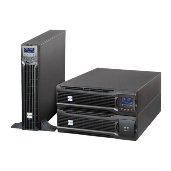
- Page 51 Optional connectivity car s it en ance communication capa ilities. Firm are t at is easily upgra a le it out a service call. Eaton DXRT 10KS31-IN Series Online UPS Mo el Dimension N.W. list: Mo el name(UPS) Size W*H*D(mm) N.W.(kg) Note DXRT 10KS31-IN(UPS)...
- Page 52 ① ④ ⑦ Intelligent slot RS232 Parallel car (optional) ② ⑤ ⑧ Dry IN/OUT MBP etection Input /Output terminal ③ ⑥ ⑨ EBM connector...
- Page 53 ① ② ③ Fuse oar cover EBM ca le EBM connector (replace EBM use)
- Page 55 It is recommen e to move t e equipment to t e installation site y using a pallet jack or a truck e ore unpacking. T e system may e installe only y quali ie electricians in accor ance it applica le sa ety regulations. T e ca inet is eavy please install it it at least t o peoples.
- Page 56 T e ca inet is eavy please see spec eig t provi e on t e carton/la el. Do not li t t e unit’s ront panel an rear panel. Discar or recycle t e packaging in a responsi le manner or store it or uture use.
- Page 57 Note t at you alrea y installe a ‘rail kit’ to rack ca inet or t is operation an ‘1U’ rail kit is recommen e to e selecte . Remove t e plastic si e cover: irst pull t e si e cover ack a certain istance t en take it out to t e rig t.
- Page 58 1. Rotate t e LCD mo el to to er irection. 2. Set up t e ‘Sta ilizer racket’ t en take t e unit into ‘Sta ilizer racket’. 1. Remove t e plastic si e cover: irst pull t e si e cover ack a certain istance t en take it out to t e rig t.
- Page 59 2. Install ‘Ear racket’ to t e unit y t e M4 scre s ( lat ea ). 3. Sli e t e unit into ‘rail kit’ make sure tig ten t e ‘rack mounting scre ’.
- Page 60 1. Set up t e ‘Extension plate’ as elo an install to ‘Sta ilizer racket’ rom UPS. 2. Take t e UPS EBM into ‘Sta ilizer racket’ in ivi ually. 3. Connect to UPS it ‘Battery po er ca le’--- Re er to rack position installing.
- Page 61 Recommen e protective evices an ca le cross-sections Recommen e upstream protection Mo el name DXRT 10KS31-IN Input roun 10mm (6AW ) Input L (L1 L2 L3) N roun 10mm (6AW ) Circuit reaker o input 100A Output L N roun 10mm (6AW )
- Page 62 T ree p ase system Hig leakage current: Eart connection essential e ore connecting supply. Common input/output sources connection T is type o connection must e carrie y quali ie electrical personnel Al ays connect t e groun ire irst 1.
- Page 63 3-1 mo el: 1-1 mo el: 3. Tie up t e AC ca le to t e rear panel. 4. Install ack t e cover o terminal lock. Connecting t e UPS to t e EBM y EBM ca le t e UPS protects t e en t e utility po er is interrupte .
- Page 64 Plug one en o t e attery ox ca le into t e attery socket on t e rear panel o t e UPS. 3. I t e UPS requires a longer ackup time increase t e num er o EBM. Be ore connecting t e attery please re er t e iring la el “+”...
- Page 65 I you or ere MBP mo el please connect t e UPS’s terminal locks rom MBP’s source etails operation please re er to MBP’s user manual. As long as t e UPS is equippe it parallel oar an parallel ca les up to 3 UPSs can e connecte in parallel to con igure a s aring an re un ant output po er.
- Page 66 Be ore installing a ne parallel UPS system please prepare t e input /output ires reakers an a main maintenance mec anical s itc or static s itc . 2) In epen ent attery packs or eac UPS. 3) Remove t e cover plate o parallel port on t e UPS connect eac UPS y one parallel ca le an make sure t e ca le is scre e...
- Page 67 5) Connect t e input an output ires. 3-1 mo el: 1-1 mo el: eneral operation nee s to ollo t e stan -alone operation requirements. 7) Mains po er-on: A ter t e mains po er ca le is connecte press any one o t e UPSs po er-on keys or more t an 1s.
- Page 68 ork in attery mo e. Or i a UPS in t e system as een turne on to t e inverter state press t e po er utton to esta lis t e orking po er or t e ne UPS an t e ne ly a e UPS ill automatically...
- Page 69 EPO on t e rear panel o UPS isconnecting t e EPO can cut o t e output o t e UPS. & Dry in is optical coupling input inter ace ic is connecte to an external s itc . A ter custom setting t e ry contact input unction it can per orm operations suc as po er on an po er o .
- Page 70 T e UPS as a grap ical LCD ive- utton. It provi es use ul in ormation a out t e UPS itsel loa status events measurements an settings. T e ollo ing ta le s o s t e in icator status an escription: In icator Color...
- Page 71 T e ollo ing ta le s o s t e Control Button Functions: Press t is utton or >100ms <1s can po er Po er on on t e ups it out utility input at t e con ition attery connecte .
- Page 72 T e Buzzer e inition as elo : B zz Fault active Continuous Over Loa 2 Beep every secon Warning active Ot er Warning active Beep every secon Beep every 4 secon s i attery lo uzzer Beep Battery output every secon Bypass output Beep every 2 minutes...
- Page 73 T e ollo ing ta le escri es t e in ormation o UPS status. Note: I ot er in icator appears see trou les ooting on c apter 7.2 or more in ormation. Operation status Cause Description Stan y mo e T e UPS is O .
- Page 74 Fault Some atal pro lems T e UPS ill cut o t e output or appene trans er to ypass mo e at once an keep alarming. Overloa T e loa excee s Some unnecessary loa s s oul e cut t e capacity o t e o one y one to re uce t e loa connecte to t e UPS.
- Page 75 Settings Sets parameters Event log Event list I enti ication [Pro uct type/mo el] / [Part/Serial num er] / [UPS/NMC irm are] T e ollo ing ta le isplays t e options t at can e c ange y t e user. Su menu Availa le settings De ault settings...
- Page 76 External [0~300] Accor ing to mo el attery AH setting Battery [ena le ] [ isa le ] [ena le ] remaining time C arger [1~12A] [2A] current Site iring [ isa le ] [ena le ] [ isa le ] ault alarm [Open] [Auto control] [Open]...
- Page 77 Be ore using t is eature t e UPS must ave een po ere y utility po er it output ena le at least once. A ter connect t e UPS attery s oul ait 10s e ore pressing t e utton or pre-c arging t e auxiliary po er supply.
- Page 78 secon s later t e ups ill s ut o n an no voltage is availa le rom t e UPS output. 5.6 L Except t e e ault UPS status summary screen t e user can get more use ul in ormation a out UPS status etaile various measurements previous event recor s...
- Page 79 By pressing on t e menu o “UPS status” t e isplay oul enter t e next UPS status menu tree. T e content o UPS status menu tree is same as t e e ault UPS status summary menu. By pressing ESC >300ms t e isplay oul return t e last main menu tree.
- Page 80 By pressing on t e menu o “Measurements” t e isplay oul enter t e next measurements menu tree. A lot o etaile use ul in ormation coul e c ecke ere Ex. t e output voltage an requency t e output current t e loa capacity t e input voltage an requency etc.
- Page 81 By pressing on t e menu o “Event log” t e isplay enter t e next event menu tree. All t e previous events alarm an ault een recor e ere. T e in ormation inclu es t e illustration t e event co e an t e precise time o en t e event appene .
- Page 82 By pressing on t e menu o “Control” t e isplay oul enter t e next control menu tree. Start Battery Test: t is is one comman t at control t e UPS to o t e attery test. Reset Fault status: en ault occurs UPS oul keep in Fault mo e an alarm.
- Page 84 By press on t e menu o “I enti ication” t e isplay enter t e next i enti ication menu tree. T e i enti ication in ormation inclu es UPS serial num er irm are serial num er mo el type e s o n ere.
- Page 87 For t e est preventive maintenance keep t e area aroun t e equipment clean an ust ree. I t e atmosp ere is very usty clean t e outsi e o t e system it a vacuum cleaner. For ull attery li e keep t e equipment at an am ient temperature o 25 C (77 F).
- Page 88 Servicing s oul e per orme y quali ie service personnel kno le gea le atteries require precautions. Keep unaut orize personnel a ay rom atteries. Batteries can present a risk o electrical s ock or urn rom ig s ort ...
- Page 89 For RT mo ule i MBP is connecte it t e UPS s oul turn t e MBS to ypass an s itc o t e input an t en replace t e EBM(s). I MBP is not connecte it t e UPS s oul turn o t e UPS an t en replace t e EBM. 1.
- Page 90 Do not iscar t e UPS or t e UPS atteries in t e tras . T is pro uct contains seale lea aci atteries an must e ispose o properly. For more in ormation contact your local recycling/ reuse or azar ous aste center.
- Page 91 T e UPS is esigne or ura le automatic operation an also alert you enever potential operating pro lems may occur. Usually t e alarms s o n y t e control panel o not mean t at t e output po er is a ecte . Instea t ey are preventive alarms inten e to alert t e user.
- Page 92 Fault co e: A502 Battery voltage is too C eck t e attery an c arger Fault lig t las es I t e attery is amage 1 eep every 1 secon . Replace it imme iately y a pro essional. Fault co e: A500 UPS c arger ault Please contact your supplier...
- Page 93 Fault co e: F305 In icates t at t e UPS Please contact your supplier Fault lamp lig ts long recti ier ault. Beep continuous. Fault co e: A307 In icates t at t e UPS Please contact your supplier Fault lamp lig ts long recti ier use ault.
- Page 94 Fault co e: F808 UPS as trans erre to T e UPS trans ers to Battery Fault lamp lig ts long ypass or ault mo e mo e i supporting t e loa . Beep continuous. ecause o overloa in Remove some o t e inverter mo e equipment rom t e UPS...
- Page 95 Fault co e: F207 Bypass ault Please contact your supplier Fault lamp lig ts long Beep continuous. Fault co e: A00E In parallel system, C eck i t e parallel ca le Fault LED is las parallel ca le connect OK. 1 eep every 1 secon isconnect Fault co e: A012...
- Page 96 Mo el name DXRT 10KS31-IN 10kVA/10kW Rate po er (Hz) Rate requency Voltage range(VAC) 110~276 (P ase voltage) Input Rate current (A) Rate voltage(VAC) Output Rate current (A) 45.5 Electrical per ormance Input P ase 3 P ase/1 P ase 40-70Hz Frequency ≥0.995...
- Page 97 Bypass AC source Source supplying t e ypass line. T e equipment can e trans erre to t e ypass line i an overloa occurs on t e UPS output or maintenance or in t e event o mal unction. Frequency converter Operating mo e use to convert t e AC-po er requency et een t e UPS input an output (50Hz ->...
- Page 98 614-40029-00...
Need help?
Do you have a question about the DXRT 10KS31-IN Series and is the answer not in the manual?
Questions and answers