Table of Contents
Advertisement
Advertisement
Table of Contents

Related Manuals for Eaton E DX Series


Summary of Contents for Eaton E DX Series
-
Page 2: Table Of Contents
Table of Contents Brief introduction 1.1 System and model description---------------------------------------------------------------------1 1.2 Description of commonly used symbols---------------------------------------------------------2 1.3 Appearance---------------------------------------------------------------------------------------------3 1.4 Product specification and performance----------------------------------------------------------4 General specification Electric performance Operating environment Installation 2.1 Unpacking & Inspection-------------------------------------------------------------------------- ---5 2.2 Input and output power cords and protective earth installation----------------------------5 2.3 Operating procedure for connecting the long backup time model UPS with the external battery ---------------------------------------------------------------------------------------8 2.4 Parallel operation--------------------------------------------------------------------------------------9... -
Page 3: Brief Introduction
Voltage level Code 220-240V~ The description followed in this manual is applicable to Eaton DX 10000HXL, DX 15000HXL and DX 20000HXL.This series are three-phase input and single-phase output long backup time, which are able to connect with the external battery bank. -
Page 4: Description Of Commonly Used Symbols
1. Brief introduction 1.2 Description of commonly used symbols The following symbols will be used in this manual. It is advisable to familiarize and understand yourself with them. Recyclable Do not dispose with ordinary trash --2-- PDF created with pdfFactory Pro trial version www.pdffactory.com... -
Page 5: Appearance
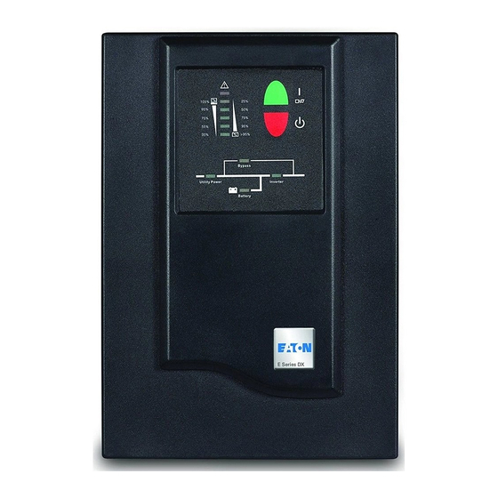
1. Brief introduction 1.3 Appearance The method, type and appearance of the input socket and output socket are vary with different areas and different client, the appearance of the products is based on what it is, this picture is just for your reference. -
Page 6: Product Specification And Performance
1. Brief introduction 1.4 Product specification and performance General specification Model 10000HXL31 15000HXL31 20000HXL31 Power Rating 10KVA/7KW 15KVA/10.5KW 20KVA/14KW Voltage range 322-461V~ Phase Three Phase Frequency 50/60Hz 50/60Hz 50/60Hz Voltage 380-415V~ Rated Input Current 51A max. 75A max. 96A max. Voltage 240VDC 240VDC... -
Page 7: Installation
2. Installation 2.1 Unpacking and inspection Unpack the packaging and check the package contents. The shipping package contains: A UPS A User manual A communication cable A battery cable (for 10000HXL31 only) If the UPS arrives damaged, or there is any missing accessory, please contact the carrier and dealer immediately. - Page 8 2. Installation Connect the input and output wires to the corresponding input and output terminals according to the following diagram. Note: you must make sure that the input and output wires and the input and output terminals are connected tightly The protective earth ground wire refers to the wire connection between the equipment which consumes electric equipment and the ground wire.
- Page 9 2. Installation Output Ground Input Ground Input Neutral Output Neutral Input Line wire A Output Line Input Line wire B Input Line wire C Input and output Terminal Block wiring diagram of 10000HXL31 Important notes: If the UPS is used in single mode, JPI and JP2 must be connected by 10AWG(6mm ).
-
Page 10: Operating Procedure For Connecting The Long Backup Time Model Ups With The External Battery
2. Installation 2.3 Operating procedure for connecting the long backup time model UPS with the external battery 1. The nominal DC voltage of external battery pack is 240VDC. Each battery pack consists of 20 pieces of 12V maintenance free batteries in series. To achieve longer backup time, it is possible to connect multi-battery packs, but the principle of “same voltage, same type”... -
Page 11: Parallel Operation
2. Installation 2.4 Parallel operation Brief introduction of the redundancy N+X is currently the most reliable power supply structure. N represents the minimum UPS number that the total load needs; X represents the redundant UPS number, i.e. the fault UPS number that the system can handle simultaneously. The bigger the X is, the higher reliability of the power system is. - Page 12 2. Installation In Parallel Wiring Diagram of 10000HXL31 --10-- PDF created with pdfFactory Pro trial version www.pdffactory.com...
- Page 13 2. Installation In Parallel Wiring Diagram of 15000HXL31/20000HXL31 --11-- PDF created with pdfFactory Pro trial version www.pdffactory.com...
-
Page 14: Operation And Operating Mode
3. Operation and Operating mode 3.1 Operation 1. Turn on the UPS with utility power supplied (in Line mode/AC mode) After you make sure that the power supply connection is correct, set the bypass breaker and the input breaker in the “ON” position first. At this time the fan rotates and the UPS supplies power to the load via the bypass. -
Page 15: Operating Mode
3. Operation and Operating mode When being powered off, the UPS will perform self-diagnosis, the Load/Battery level LEDs will be turned on and then off one after another in ascending order. Finally no any display is shown on the display panel and no voltage is available from the UPS output. - Page 16 3. Operation and Operating mode 2. Battery mode The display panel in battery mode is shown in the following diagram Fig.3-2. The battery LED and the INV LED are turned on. The displayed number of the battery level LEDs will be turned on in accordance with the battery capacity.
- Page 17 3. Operation and Operating mode Fig 3-3 UPS bypass mode diagram 2) Other indications on the display panel are the same in utility mode. 3) The UPS does not have the backup function when it is in bypass mode. The power used by the load is supplied from the utility power via internal filter.
- Page 18 3. Operation and Operating mode AS400 port (optional): This optional AS400 card provides dry contact closure signal “OPEN” or “CLOSE”. Following are the pin assignment and the descriptions of AS400 card: This series UPS only requires minimal maintenance. The battery used for standard models are value regulated sealed lead-acid maintenance free.
-
Page 19: Battery Maintenance
4. Battery maintenance batteries and also offers the protective function of overcharging and over-discharging. The UPS should be charged once every 4 to 6 months if it has not been used for a long time. In hot climates, the battery should be charged every 2 months. The standard charging time should be at least 12 hours. -
Page 20: Notes For Battery Disposal And Battery Replacement
5. Notes for battery disposal and battery replacement 1) Before disposing of batteries, remove conductive jewelry such as necklace, wrist watches and rings. 2) If it is necessary to replace any connection cables, please purchase the original materials from the authorized distributors or service centers, so as to avoid overheat or spark resulting in fire due to insufficient capacity. -
Page 21: Troubleshooting
6. Troubleshooting Problem Possible cause Solution The #1 Fault LED and the The UPS shutdown due to Make sure the UPS is not overloaded; #6 LED are turned on, the internal overheat the air vents are not blocked and the buzzer beeps continuously ambient temperature is not too high. - Page 22 6. Troubleshooting Problem Possible cause Solution Bypass breaker in “OFF” Set the bypass breaker in “ON” The utility power is normal, but the UPS can not turn in position position. line mode Battery discharging time Battery not yet been fully Keep UPS connected to utility power diminishes charged...
-
Page 23: Appendix 1 Display Panel
Appendix 1 display panel Power ON/OFF: To turn on the UPS simply by pressing the “ON” button on the front panel continuously for 1 second. Press the “OFF” button on the front panel continuously for 1 second to turn off the UPS. Bypass LED (orange LED): Whenever the bypass LED is turned on, it shows that the loading current is supplied directly from the utility power. -
Page 24: Appendix 2 Led Indication And Alarm Functions
Appendix 2 LED indication and alarm functions LED display Operating state Alarm warning 0~35% none ● ● ● Load capacity 36%~55% none ● ● ● ● Load capacity 56%~75% none Utility ● ● ● ● ● Load Power capacity Mode 76%~95% none ●... - Page 25 Appendix 2 LED indication and alarm functions 61%~80% Beep once every ● ● ● ● ● ● 4 sec Battery Battery capacity Mode 81%~100 Beep once every 4 sec ● ● ● ● ● ● ● Battery capacity Beep once every ↑...
- Page 26 Appendix 2 LED indication and alarm functions Charger battery Beep once every ● ↑ ↑ ↑ ★ failed Continuously ● ● ● ↑ ↑ BAT SCR failed beep Beep once every ● ● ● ↑ ↑ ↑ ↑ Fan abnormal Continuously ●...
Need help?
Do you have a question about the E DX Series and is the answer not in the manual?
Questions and answers