Table of Contents
Advertisement
Questo manuale d'istruzione è fornito da trovaprezzi.it. Scopri tutte le offerte per
RT2U
Copyright © 2016 EATON
All rights reserved.
9PX 1-3 KVA US_EN
o cerca il tuo prodotto tra le
migliori offerte di Gruppi di Continuità
Eaton 9PX 1000i
9PX 700 RT
9PX 1000 RT
9PX 1000GRT
9PX 1500 RT
9PX 1500GRT
9PX 2000 RT
9PX 2200 GRT
9PX 3000 RT
9PX 3000 GRT
9PX 3000 GLRT
9PX EBM 36V RT
9PX EBM 48V RT
9PX EBM 72V RT
Installation
and user manual
Advertisement
Table of Contents

Subscribe to Our Youtube Channel
Related Manuals for Eaton 9PX 1000i RT2U


Summary of Contents for Eaton 9PX 1000i RT2U
- Page 1 9PX 2000 RT 9PX 2200 GRT 9PX 3000 RT 9PX 3000 GRT 9PX 3000 GLRT 9PX EBM 36V RT 9PX EBM 48V RT 9PX EBM 72V RT Installation and user manual Copyright © 2016 EATON All rights reserved. 9PX 1-3 KVA US_EN...
- Page 2 SAFETY INSTRUCTIONS SAVE THESE INSTRUCTIONS. This manual contains important instructions that should be followed during installation and maintenance of the UPS and batteries. The 9PX models that are covered in this manual are intended for installation in an environment within 0 to 40°C, free of conductive contaminant. This equipment has been tested and found to comply with the limits for a Class A digital device, pursuant to Part 15 of the FCC Rules.
- Page 3 • The system is not for use in a computer room AS DEFINED IN the standard for the Protection of Information Technology Equipment, ANSI/NFPA 75 (US installations only). Contact Eaton resellers to order a special battery kit, if needed to meet the ANSI/NFPA 75 requirement.
- Page 4 • During the replacement of the Battery Module, it is imperative to use the same type and number of element as the original Battery Module provided with the UPS to maintain an identical level of performance and safety. If there are any questions, don’t hesitate to contact your EATON representative.
-
Page 5: Table Of Contents
Connection with a HotSwap MBP module (optional accessory) ........26 4. Communication .................. Communication ports ....................28 UPS remote control functions ..................29 Eaton Intelligent Power Software suite ...............31 5. Operation..................... Start-up and Normal operation ..................32 Starting the UPS on Battery ..................32 UPS Shutdown ......................32... -
Page 6: Introduction
Before installing your 9PX, please read the booklet presenting the safety instructions. Then follow the indications in this manual. To discover the entire range of EATON products and the options available for the 9PX range, we invite you to visit our web site at www.eaton.com/powerquality or contact your EATON representative. - Page 7 - causing hours of lost productivity and expensive repairs. With the Eaton 9PX, you can safely eliminate the effects of power disturbances and guard the integrity of your equipment. Providing outstanding performance and reliability, the Eaton 9PX’s unique benefits include: • True online double-conversion technology with high power density, utility frequency independence, and...
-
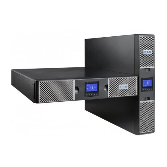
Page 8: Presentation
2. Presentation Standard installations Tower installation Rack installation Description Weights Dimensions (inch/mm) (lb/kg) D x W x H 9PX700RT 36.4 / 16.5 17.7 x 17.3 x 3.4 / 450 x 440 x 86.5 9PX1000RT 36.4 / 16.5 17.7 x 17.3 x 3.4 / 450 x 440 x 86.5 9PX1000GRT 38.6 / 17 .5 17.7 x 17.3 x 3.4 / 450 x 440 x 86.5... -
Page 9: Rear Panels
2. Presentation Rear panels 9PX 700RT / 9PX 1000RT / 9PX 1500RT Socket for connection to AC power source Slot for optional communication card Relay output contact Connector for additional battery module Primary group: outlets for connection of critical equipment Group 1: programmable outlets for connection of equipment Group 2: programmable... -
Page 10: Accessories
2. Presentation 9PX EBM 36V/48V Connectors for battery modules (to the UPS or to the other battery modules) Connectors for automatic recognition of battery modules 9PX EBM 72V Accessories Part number Description 9PXEBM36RT2U 9PXEBM48RT2U Extended battery module 9PXEBM72RT2U Rack kit 9PX Network-MS Network card Modbus-MS... -
Page 11: Control Panel
2. Presentation Control panel The UPS has a five-button graphical LCD. It provides useful information about the UPS itself, load status, events, measurements and settings. Online mode Fault indicator (green) indicator (red) Battery mode Bypass mode indicator (orange) indicator (orange) Online mode 100% 100% 2.7k W 19min 3.0kVA 1EBM Efficiency: 94 % Escape Down Enter On/Off button The following table shows the indicator status and description: Indicator... -
Page 12: Lcd Description
2. Presentation LCD description After 5 minutes of inactivity, the LCD displays the screen saver. The LCD backlight automatically dims after 10 minutes of inactivity. Press any button to restore the screen. Operation status Online mode 100% 100% Load/equipment status 2.7kW 19min Battery status... -
Page 13: Display Functions
[Product type/model] / [Part/Serial number] / [UPS/NMC firm- ware] / [Com card IPv4], [Com card IPv6], [Com card MAC] Registration Links to Eaton registration website User settings The following table displays the options that can be changed by the user. - Page 14 2. Presentation Submenu Available settings Default settings Output voltage [100V] [110V] [120V] [125V] [120V] [200V] [208V] [220V] [230V] [240V] [208V] Output frequency Mode: [Normal] [Converter] [Marine] [Normal] Frequency can be changed in Frequency [Converter] mode In [Marine] mode output frequency follows input frequency Output mode Mode: [Industrial] [IT] [Custom]...
- Page 15 2. Presentation Submenu Available settings Default settings Automatic battery In ABM cycling mode : test [No test] [Every ABM cycle] [Every ABM cycle] In constant charge mode: [No test] [Every day] [Every week] [Every week] [Every month] Low battery [Capacity] [0%] … [100%] [0%] warning [Runtime] [0min] …...
- Page 16 2. Presentation Submenu Available settings Default settings [Relay] [DB9-1] [DB9-7] [DB9-8] Output signals Sets events or fault that will actuate Output signal parameters through external contact connector or RS232 port [Relay]: [On bat] [Low bat] [Bat fault] [Relay] [Bypass] [Bypass] [UPS OK] [Load protected] [Load powered] [General alarm] [Ext.
-
Page 17: Installation
3. Installation Inspecting the equipment If any equipment has been damaged during shipment, keep the shipping cartons and packing materials for the carrier or place of purchase and file a claim for shipping damage. If you discover damage after acceptance, file a claim for concealed damage. To file a claim for shipping damage or concealed damage: 1. File with the carrier within 15 days of receipt of the equipment; 2. Send a copy of the damage claim within 15 days to your service representative. Check the battery recharge date on the shipping carton label. - Page 18 3. Installation Checking the accessory kit 9PX 1000GRT / 9PX 1500GRT / 9PX 2200GRT / 9PX 3000GRT • Verify that the following additional items are included with the UPS: Quick start 9PX UPS Connection cable to AC-power source Mounting kit for 19-inch enclosures 2 connection cables for the protected 2 supports for tower position equipment...
- Page 19 3. Installation Checking the accessory kit 9PX 3000GLRT • Verify that the following additional items are included with the UPS: Quick start 9PX UPS Connection cable to AC-power source Mounting kit for 19-inch enclosures RS232 communication cable 2 supports for tower position Elements supplied depending on the version or USB communication cable optional...
- Page 20 3. Installation • If you ordered an optional Extended Battery Module (EBM), verify that the following additional items are included with the EBM: Battery power cable with attached battery detection cable Stabilizer bracket (4 screws included) Rack kit for 19-inch enclosures (optional) EBM Installation manual.
-
Page 21: Connecting The Internal Battery
3. Installation Connecting the internal battery Do not connect the UPS to utility until installation is completed. To connect the UPS: 1. Remove the center cover of the front panel. 2. Push left cover toward to right direction. 3. Open the left side of the front panel. A ribbon cable connects the LCD control panel to the UPS. -
Page 22: Connecting The Ebm(S)
3. Installation Connecting the EBM(s) A small amount of arcing may occur when connecting an EBM to the UPS. This is normal and will not harm personnel. Insert the EBM cable into the UPS battery connector quickly and 1. Plug the EBM power cable(s) into the battery connector(s). Up to 4 EBMs may be connected to the UPS. -
Page 23: Tower Installation
3. Installation Tower installation If you ordered other UPS accessories, refer to specific user manuals to check the tower installation with the UPS. To install the cabinet: 1. Place the UPS on a flat, stable surface in its final location. 2. Always keep 6" or 150 mm of free space behind the UPS rear panel for ventilation. 3. If installing additional cabinets, place them next to the UPS in their final location. • Adjustment of the orientation of the LCD panel and of the logo. • Adjustment of the angle of vision of the LCD panel. -
Page 24: Rack Installation
3. Installation Rack installation • Rack mounting of UPS, EBM, and accessory modules. Follow steps 1 to 4 for module mounting on the rails. The rails and necessary hardware are supplied by EATON. Page 24 9PX 1-3 KVA US_EN... -
Page 25: Ups Connection Without Hotswap Mbp Module
3. Installation UPS connection without HotSwap MBP module Check that the indications on the name plate located on the back of the UPS correspond to the AC-power source and the true electrical consumption of the total load. 1. 9PX 2000RT / 3000RT : connect the UPS input socket to the AC-power source. -
Page 26: Connection With A Hotswap Mbp Module (Optional Accessory)
3. Installation Connection with a HotSwap MBP module (optional accessory) The HotSwap MBP module makes it possible to service or even replace the UPS without affecting the connected loads. 9PX 2000RT 1. Connect the input on the HotSwap MBP module to the AC-power source. - Page 27 3. Installation 9PX 2200GRT & 9PX 3000GRT 1. Connect the input on the HotSwap MBP module to the AC-power source. 2. Connect the UPS input cable the “UPS Input socket” on the HotSwap MBP module. 3. Connect the UPS outlet to the “UPS Output”...
-
Page 28: Communication
USB or RS232 communication port on the UPS. The UPS can now communicate with EATON power management software. Installation of the communication cards It is not necessary to shutdown the UPS before installing a communication card. -
Page 29: Ups Remote Control Functions
4. Communication UPS remote control functions Programmable Signal Inputs The 9PX incorporates 3 programmable signal inputs: one Remote Power Off (RPO) input terminal, one Remote On/Off (ROO) input terminal, one RS-232 input (pin-4). Signal inputs can be configured (see Settings > Com settings > Signal Input on page 15) to have one of the following functions: Function Description No function, please choose a function if you want to use input signal Remote Power Off (RPO) is used to shutdown the UPS remotely Remote On/Off allows remote action of button to switch On/Off the UPS. - Page 30 4. Communication • Remote On/Off (ROO) Remote On/Off allows remote action of button to switch On/Off the UPS. When contact changes from open to closed, the UPS is switched-on (or stays On). When contact changes from closed to open, the UPS is switched-off (or stays Off). On/Off control via button has priority over the remote control.
-
Page 31: Eaton Intelligent Power Software Suite
Eaton Software suite provides up-to-date graphics of UPS power and system data and power flow. It also gives you a complete record of critical power events, and it notifies you of important UPS or power information. If there is a power outage and the 9PX UPS battery power becomes low, Eaton Software suite can automati- cally shut down your computer system to protect your data before the UPS shutdown occurs. Page 31 9PX 1-3 KVA US_EN... -
Page 32: Operation
Standby mode, and the indicator turns off. Operating modes The Eaton 9PX front panel indicates the UPS status through the UPS indicators, see page 11. Online mode During Online mode, the indicator illuminates solid and the UPS is powered from the utility. -
Page 33: Return Of Ac Input Power
Setting High Efficiency mode In High Efficiency mode, the UPS operates normally on Bypass and transfers to Online (or Battery) mode in less than 10 ms when utility fails. T ransfers to High Efficiency mode will be active after 5 minutes of Bypass voltage monitoring: if Bypass quality is not in tolerance, then the UPS will remain in Online mode. Eaton recommends to use the HE mode only to protect IT equipment. To set the High Efficiency mode: 1. Select Settings, In/Out settings, and High Efficiency mode. 2. Select Enabled and Enter to confirm. -
Page 34: Configuring Battery Settings
5. Operation Qualify Bypass The default setting (“In spec”) allows a transfer to Bypass only when Bypass is within the following specifi- cations: • Bypass voltage is between the “Bypass Voltage Low Limit” and “Bypass Voltage High Limit” settings • Bypass frequency is within nominal frequency 5%. You can prohibit Bypass (”Never”) or always allow Bypass with no specification checking (“Always”). For “Always on UPS Fault, ” transfer to Bypass is always made on UPS fault; otherwise, operation proceeds as with the default setting. -
Page 35: Ups Maintenance
When to replace batteries Eaton UPS batteries have an expected life span of 3-5 years. After 4 years of operation, the UPS will provide a battery replacement notification reminding you that your batteries are nearing the end of their useful life. You should take proactive steps to ensure you replace your batteries for optimal operation and reliability. -
Page 36: Replacing Batteries
6. UPS maintenance Replacing batteries DO NOT DISCONNECT the batteries while the UPS is in Battery mode. Batteries can be replaced easily without turning off the UPS or disconnecting the load. If you prefer to remove input power to change the batteries, see "UPS Shutdown" on page 32. Consider all warnings, cautions, and notes before replacing batteries. - Page 37 6. UPS maintenance To replace the battery pack: 1. Remove the center cover of the front panel. 2. Push left cover toward to right direction. 3. Open the battery door. 4. Disconnect the battery connectors. A ribbon cable connects the LCD control panel to the UPS. Do not pull on the cable or disconnect it. 5.
-
Page 38: Replacing The Ups Equipped With A Hotswap Mbp
6. UPS maintenance Replacing the UPS equipped with a HotSwap MBP The HotSwap MBP module makes it possible to service or even replace the UPS without affecting the connected loads. Maintenance 1. Set switch to Bypass position. The red LED on the HotSwap MBP module goes ON, indicating that the load is supplied directly with AC input source power. -
Page 39: Troubleshooting
7. Troubleshooting The Eaton 9PX are designed for durable, automatic operation and also alert you whenever potential ope- rating problems may occur. Usually the alarms shown by the control panel do not mean that the output power is affected. Instead, they are preventive alarms intended to alert the user. -
Page 40: Silencing The Alarm
For critical applications, immediate replacement may be available. Call the Help Desk for the dealer or distributor nearest you. CE compliance contact • Eaton I.F . SAS - 110 Rue Blaise Pascal - 38330 Montbonnot St Martin – France. Page 40 9PX 1-3 KVA US_EN... -
Page 41: Specifications
8. Specifications Model specifications Bypass Input AC/DC DC/AC Outpout Filter Boost Inverter Filter DC/DC Charger Battery Table 1. Power Module model list Model Power ratings 9PX700RT 700VA / 630W 9PX1000RT 1000VA / 900W 9PX1000GRT 1000VA / 900W 9PX1500RT 1500VA / 1350W 9PX1500GRT 1500VA / 1350W 9PX2000RT... - Page 42 8. Specifications Table 4. Electrical input Nominal frequency 50/60Hz auto-sensing Frequency range 40-70Hz before transfer to battery Bypass voltage range -20% / +15% of nominal value (default) Noise filtering Input EMC filter Model Default input Input nominal voltages Input voltage window (Voltage/Max current) at rated load 9PX700RT...
- Page 43 8. Specifications Table 6. Electrical output Normal mode Efficiency mode Battery mode All models ±1% ±2% Voltage regulation 89.9% for 700 LV models 95.3% for 700 LV models 83% for 700 LV models Efficiency 90.3% for 1K LV models 95.8% for 1K LV models 83% for 1K LV models 90.2% for 1K G models 96% for 1K G models...
- Page 44 8. Specifications Table 8. Environmental and safety IEC/EN 62040-1 IEC/EN 62040-2 : Cat. C1 IEC/EN 62040-3 Certifications UL1778 5th edition CSA 22.2 CISPR22 Class B EMC (Emissions)* FCC part 15 Class B / ICES-003 IEC 61000-4-2, (ESD): 8 kV Contact Discharge / 15 kV Air Discharge IEC 61000-4-3, (Radiated field): 10 V/m IEC 61000-4-4, (EFT): Power (Coupling network) 4 kV / Ethernet (Coupling clamp) 2 kV...
-
Page 45: Glossary
9. Glossary Bypass AC source Source supplying the bypass line. The equipment can be transferred to the by- pass line if an overload occurs on the UPS output, for maintenance or in the event of a malfunction. Frequency converter Operating mode used to convert the AC-power frequency between the UPS input and output (50Hz ->... - Page 46 Page 46 9PX 1-3 KVA US_EN...
Need help?
Do you have a question about the 9PX 1000i RT2U and is the answer not in the manual?
Questions and answers