Table of Contents
Advertisement
Quick Links
Installation, Operation, Cleaning and Maintenance Manual
3765 Champion Boulevard
Winston-Salem, NC 27105
(336) 661-1992 Fax: (336) 661-1660
Toll-free: 1 (800) 858-4477
Issue Date: 6.10.21
Manual P/N
For machines beginning with S/N W2110103481and above
2674 N. Service Road, Jordan Station
Ontario, Canada L0R 1S0
(905) 562-4195 Fax: (905) 562-4618
Toll-free: 1( 800) 263-5798
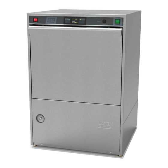
High Temperature
Undercounter
Dishwasher
Model:
383HT M2
Hot water sanitizing with 4kW built-in
stainless steel electric booster
Option:
6kW built-in electric stainless steel booster
0514616
rev. -A
Printed in the USA
Advertisement
Chapters
Table of Contents

Related Manuals for Moyer Diebel 383HT M2


Summary of Contents for Moyer Diebel 383HT M2
- Page 1 Installation, Operation, Cleaning and Maintenance Manual High Temperature Undercounter Dishwasher Model: 383HT M2 Hot water sanitizing with 4kW built-in stainless steel electric booster Option: 6kW built-in electric stainless steel booster Issue Date: 6.10.21 Manual P/N 0514616 rev. -A For machines beginning with S/N W2110103481and above 3765 Champion Boulevard 2674 N.
- Page 2 National Service Department In Canada: In the USA: Toll-free: (800) 263-5798 Toll-free: (800) 858-4477 Tel: (905) 562-4195 Tel: (336) 661-1556 Fax: (905) 562-4618 Fax: (336) 661-1660 email: service@moyerdiebellimited.com email: service@championindustries.com ATTENTION The model no., serial no., voltage, Hz and phase are needed to identify your machine and to answer questions.
- Page 3 Product Registration REGISTER YOUR PRODUCT to ACTIVATE YOUR WARRANTY. 4:34 PM Three ways to register: • Use your mobile device to scan the QR code located on the front panel of your machine or enter our URL http://www.moyerdw.us/383HT. • Visit our website at: www.moyerdiebel.com/warranty-registration •...
- Page 4 Product Registration PRODUCT REGISTRATION BY FAX COMPLETE THIS FORM AND FAX TO: (336) 661-1660 in the USA 1-(800) 204-0109 in Canada PRODUCT REGISTRATION CARD Model Serial # Date of Installation: Company Name: Address: (Street) Province Postal Code Telephone #: ( Contact: Installation Company: Address:...
- Page 5 Revision History Revision History Specifications are subject to change based on continual product improvement. Equipment owners may request a revised manual, at no charge, by calling 1 (800) 858-4477 in the USA or by calling 1 (800) 263-5798 in Canada. Revision Revised Serial Number...
- Page 6 Machines found to have issues related to installation procedures, or DISCLAIMER OF WARRANTIES AND LIMITATIONS OF LIABILITY. MOYER DIEBEL’S delays of any kind, will not be covered by Moyer Diebel and the sole WARRANTY IS ONLY TO THE EXTENT REFLECTED ABOVE. MOYER DIEBEL responsibility of the equipment purchaser.
-
Page 7: Table Of Contents
Table of Contents Table of Contents Revision History ..................................i Limited Warranty ..................................ii Installation ............................1 Receiving and Placement ........................1 Installation Codes ..........................2 Water Connection ..........................3 Drain Connection ..........................4 Electrical Connection ...........................6 Detergent Set-up ............................9 Rinse-Aid Set-up ...........................10 Operation ............................12 Control Panel Description ........................ - Page 8 Safety Symbols Safety Symbols The following symbols are used throughout this manual to alert the reader to important information. WARNING: Warnning statements indicate a condition or practice that can result in personal injury or possible death. CAUTION: Caution statements indicate a condition or practice that can result in damage to the machine or associated equipment.
- Page 9 Receiving/Placement/Installation Codes Receiving 1. Inspect the outside of the dishwasher carton for signs of damage. 2. Remove the carton and inspect the dishwasher for damage. 3. Check for any options or accessories that may have shipped with your dishwasher. 4. Register by fax using the form at the front of this manual or online at: www.moyerdiebel.com/warranty-registration.
- Page 10 Installation Installation Codes The installation of the dishwasher must comply with all local electrical, plumbing, health, and safety codes or in the absence of local codes, installed in accordance with the applicable require- ments in the National Electrical Code, NFPA 70, Canadian Electrical Code (CEC), Part 1, CSA C22.1;...
-
Page 11: Limited Warranty
Installation Water Connection Connect the plumbing in accordance with the specifications below. WATER MINIMUM 1/2" NPT OR LARGER HOT WATER SUPPLY LINE. CAUTION: To prevent damage to the dishwasher supply valves, the installing plumber must thoroughly flush debris from the water supply line before connecting it to the dishwasher. -
Page 12: Drain Connection
Installation Drain Connection Connect the drain in accordance with the specifications below. DRAIN CAUTION: The dishwasher drain connection must comply with all local plumbing, health and safety codes. Damage caused by improper installation is not covered by the limited warranty THE DISHWASHER IS EQUIPPED WITH A 4FT / 1.2 m CLEAR BRAIDED DRAIN HOSE AND A 3/4"... - Page 13 Installation Drain Connection DRAIN MUST BE VENTED TO PREVENT SYPHONING DRAIN HOSE 3/4 IN. MNPT HOSE ADAPTER 1-1/2 IN. WYE OPTIMUM FITTING FT. MAX OFF FLOOR LEVEL Fig. 3 Configuring the drain line. DO NOT REPOSITION THE DRAIN HOSE DO NOT ADD AN EXTENSION TO THE DRAIN HOSE Fig.
-
Page 14: Electrical Connection
Installation Electrical Connection Electrocution may occur when working on ener- WARNING: gized circuits. Disconnect power at the main breaker or service disconnect switch, then lock out and tag it to indicate that work is being performed on the circuit. CAUTION: Electrical connections must be made AFTER the plumbing installation. - Page 15 Installation Electrical Connection (continued) REMOVE THE LEFT SCREW ON THE FRONT LIP OF THE TERMINAL BOX. LIFT AND REMOVE THE COVER TO ACCESS THE TERMINAL BLOCK. TERMINAL ENCLOSURE Fig. 6 STOP A 30" / 76 cm SERVICE LOOP MUST BE PROVIDED BEHIND THE UNIT FOR STRAIN-RELIEF GROUND LUG...
- Page 16 Installation ! VERY IMPORTANT ! MACHINE START-UP (Chemical Dispensing Pumps) PLACE THE CHEMICAL CONTAINERS AS CLOSE TO THE MACHINE AS POSSIBLE. DO NOT ELEVATE THE CONTAINERS ABOVE THE FINISHED FLOOR ! VERY IMPORTANT ! Contact a chemical supplier for detergent and rinse-aid chemicals. The chemical supplier must adjust the chemical dispensing pumps for water hardness and food soil types The detergent and rinse-aid pumps are...
-
Page 17: Detergent Set-Up
Installation Detergent Set-up USE A NON-CHLORINATED COMMERCIAL GRADE DETERGENT. WASH TANK CAPACITY: 4 US GAL / 3.3 IMP. GAL / 15 L. DETERGENT INJECTION POINT ON WASH TANK REAR WALL. DETERGENT DISPENSING TIME WAS SET AT THE FACTORY. The final adjustment should be performed by the chemical supplier. DETERGENT PUMP IS LOCATED BEHIND LOWER FRONT PANEL. -
Page 18: Rinse-Aid Set-Up
Installation Rinse-aid Set-up CONSULT CHEMICAL SUPPLIER FOR THE CORRECT RINSE-AID. R /A RINSE WATER PER RACK: 0.84 US GAL / 0.7 IMP. GAL / 3.2 L. RINSE-AID INJECTION POINT IS INTO THE RINSE ARMS. RNISE-AID VOLUME WAS SET AT THE FACTORY. The final adjustment should be performed by the chemical supplier. - Page 19 Installation Prime the Rinse-aid Pump Place the rinse-aid pick-up tube in a full container of rinse aid. Push the dishwasher power switch ON. The dishwasher will automatically fill with water. Wait twenty minutes or until the temperature display indicates a minimum of 1 50°F/66°C.
-
Page 20: Operation
Operation Control Panel Description A - ON-OFF/Drain power switch tur turned on and the automatic drain cycle when tur B - LCD screen displays machine status: including temperatures, operation, heating and autoclean functions such as, wait, and in-cycle. TEMPERATURE DISPLAY indicates water temperature and displays operation codes for the operator. -
Page 21: Loading Wares
Operation Operation - Loading Wares REMOVE LARGE FOOD PARTICLES AND DEBRIS BEFORE LOADING WARES. LOAD PLATES IN A PEG RACK. BOWLS AND GLASSES IN A FLAT-BOTTOM RACK. LOAD SILVERWARE IN A SINGLE LAYER IN A FLAT-BOTTOM RACK. LOAD POTS, PANS, AND UTENSILS UPSIDE DOWN IN A FLAT-BOTTOM RACK. DO NOT OVERLOAD RACK AND ONLY WASH ONE RACK AT A TIME. - Page 22 Parameter Setting Instructions PARAMETER SETTINGS INSTRUCTIONS PARAMETER SETTING INSTRUCTIONS 0514058 REV A -30-MAR-2021 CAUTION: Parameter changes must be made by qualified personnel only. Locate control board shown below: (LCD SCREEN) Open door. WASH TEMPERATURE ADJUSTMENT in cycle wait PRESS BUTTON TO CYCLE THROUGH AVAILABLE VALUES The following parameters may be changed...
-
Page 23: Operation Display
Operation OPERATIONAL DISPLAY The screen displays the operational status of the machine throughout the cycle. • Start-up Sequence 1. When power switch is turned ON, system information screen will show briefly. 2. This shows firmware version, parameter settings, and cycle counts. -
Page 24: Wash Cycle
Operation Operational Display (continued) WASH CYCLE WASH 1. The status indicator shows cycle progress. 2. In-cycle light is illuminated. DRAIN 1. When the wash cycle is complete the machine will drain all of the water and refill with fresh hot water. RINSE 1. - Page 25 Operation Operation - Rinse Sentry, Auto-Clean, Drain Mode RINSE SENTRY AUTOCLEAN DRAIN 1. When machine is turned o reen with the status indicator is shown. 2. This takes approximately 2-1/2 minutes. 3. When complete, open door, clean screens and wash/rinse arms and allow machine interior to air dry.
-
Page 26: Cleaning
Cleaning Cleaning Clean the machine at the end of each meal period, every 2 hours of continuous operation, and at the end of the day. CAUTION: Dishwasher surfaces may be hot. Cleaning chemicals may be caustic to the skin and eyes. Wear protective clothing and eye protection when handling chemicals and cleaning the machine. -
Page 27: Deliming
Cleaning Cleaning - Deliming WARNING: Death or serious injury may result when deliming solution is mixed with sodium hypochlorite (chlorine bleach) sanitizing agent. Mixing may cause hazardous gases to form. Deliming solution and other acids must never be mixed with chlorine, iodine, bromine, or fluorine. -
Page 28: Maintenance
Maintenance Maintenance - Schedules Daily Maintenance Check all of the wash arm and rinse arm spray jets and clean as necessary. Make sure the water supply is on and the drain is not clogged. Check the temperature display and ensure it is operating. Make sure the dish racks are in good condition. -
Page 29: Troubleshooting Chart
Maintenance Maintenance - Troubleshooting Chart Condition Cause Solution Dishwasher will not run. Door not closed. Close door completely. Main power OFF. Check breaker on panel. Dishwasher OFF. Turn dishwasher power switch ON. Low or no water. Main water supply off. Open supply valve. -
Page 30: Timing Chart
Timing Chart... - Page 31 SINGLE PHASE...
- Page 32 Service Replacement Parts Service Replacement Parts Illustrations Page Wash Pump/Motor Assembly ............................2 Booster ......................................4 Control Panel ....................................6 Power Wiring Box ..................................8 Fill Valve ....................................1 0 Wash and Rinse Spray Arms ............................1 2 Hoses and Drain Pump ..............................1 4 Panels and Door ..................................16 Upper Tank ....................................18 Rear Tank ....................................20...
- Page 33 Pump/Motor...
- Page 34 Pump/Motor Item Part Description Qty. 0512340 SCREW, M4, PHIL, PAN HD. 0512341 IMPELLER HOUSING COVER 114144 NUT, M6 (LEFT-HAND THREAD) 0501501 WASHER, LOCK, 1/4" 0501478 WASHER, PLAIN, 17/64" 0512345 IMPELLER 114139 SEAL, PUMP 110285 GASKET, PUMP 114137 PLATE, PUMP BACKING 107337 NUT, M4 0512101-1...
-
Page 35: Booster
Booster... - Page 36 Booster Item Part Description Qty. 0513310 THERMISTOR 0513314 TEE, RINSE 1/2" HB X 3/8" NPT X 1/8" NPT BRASS 0512985 CLAMP, HOSE 107417 HOSE, RUBBER 1/2" ID X 0.84" OD 108954 NUT, GRIP, 6-32 W/NYLON INSERT SST 110562 THERMOSTAT, FIXED, SNAP, 240ºF 0513880 PLUG, 3/8"...
-
Page 38: Control Panel
Control Panel Item Part Description Qty. 0512221 SWITCH, ROCKER DPST 250V NEON 0513916 LABEL, FACIA 383HT M2 0512320 GASKET, STEAM 0512357 STANDOFF, LED DISPLAY BOARD 0512978 SCREW 6-18 X 1/4 PAN HEAD PHILLIPS SS 0513915 PANEL, FACIA 383HT M2 0503580... -
Page 39: Power Wiring Box
Power Wiring Box... - Page 40 Power Wiring Box Item Part Description Qty. 0512472 LABEL, CONNECTION BOX 0313396 COVER, BOX WIRING 0313395 BOX, WIRING 0503638 SCREW, 6-32 X 1/4" 103310 LUG, GROUND 0512185 SCREW, 1/4-20 X 3/8" 0509527 BLOCK, TERMINAL, 4-POLE 0501412 SCREW, 10-32 X 3/8", TRUSS HD. 107964 BUSHING, STRAIN RELIEF, SMALL 0512432...
-
Page 41: Fill Valve
Fill Valve... - Page 42 Fill Valve Item Part Description Qty. 0512853 VALVE, WATER INLET 115VAC/60/1 (Includes Items 2 and 3) 0512861 COIL, 115VAC/60/1, 7W 0512860 KIT, REPAIR SOLENOID VALVE 0512185 BOLT, HEX FLANGE 1/4-20 X 3/8" SST 0313862 BRACKET, VALVE...
-
Page 43: Wash And Rinse Spray Arms
Wash and Rinse Spray Arms... - Page 44 Wash and Rinse Spray Arms Item Part Description Qty. 0501478 WASHER, 17/64 id X 9/16" OD SST 107967 NUT, GRIP 1/40-20 NYLON INSERT SST 0514251-1 HUB, UPPER SPRAY ARM 107873 WASHER, PACKING 110215 PLUG, UPPER MANIFOLD 0512133 O-RING, 2-1/8" OD X 1-3/4" ID X 3/16" 0712749 BEARING ASSEMBLY H34998...
-
Page 45: Hoses And Drain Pump
Hoses and Drain Pump... - Page 46 Hoses and Drain Pump Item Part Description Qty. 0502571 CLAMP, HOSE 0512120 HOSE, UPPER WASH ARM 0503679 CLAMP, HOSE GEAR-TYPE SST 107417 HOSE, RUBBER 1/2" 1D X .84" OD 0514615 FITTING, MOLDED RINSE 100500 BREAKER, VACUUM 1/2" 0508366 KIT, REPAIR VACUUM BREAKER 201029-1 NUT, LOCK 1/2"...
-
Page 47: Panels And Door
Panels and Door... - Page 48 Panels and Door Item Part Description Qty. 0312905 WRAP, OUTER PANEL 0512930 GASKET, DOOR, 1/8" X 7/8" 22-5/8" 0313863 PANEL, FRONT 0713141 DOOR 0512953 GASKET, RH DOOR HINGE 0512854 SPRING, DOOR 0312892 ARM, DOOR SPRING 0503745 SCREW, 8-32 X 3/16" PHIL. SST 0312908 ACTIVATOR, DOOR SWITCH 0512954...
-
Page 49: Upper Tank
Upper Tank... - Page 50 Upper Tank Item Part Description Qty. 0713871 SCREEN, SCRAP 0512953 GASKET, RH DOOR HINGE 0307369 PLATE, NUT 4-40 0312948 BRACKET, SWITCH DOOR 0501379 SWITCH, DOOR 15A 0501437 SCREW, 4-40 X 1/2" PAN HEAD PHILS. SST 108954 NUT, GRIP 6-32 W/NYLON INSERT SST 108418 PLUG, 1/2"...
- Page 51 Tank Rear...
- Page 52 Tank Rear Item Part Description Qty. 0503580 NUT, 10-32 SST 0513645 CLIP 0313865 BRACKET, SENSOR 0513831 SENSOR, LEVEL H450134 CLAMP, HOSE H160121 HOSE, AIR 0512761 CLAMP, DOUBLE CONDUIT B502523 CLAMP, 3/4" PLATED STRAP 107967 NUT, GRIP, 1/4-20 W/NYLON INSERT SST H25010 TRAP, AIR H25263...
- Page 53 Chemical Pumps...
- Page 54 Chemical Pumps Item Part Description Qty. 0505483 LABEL, RINSE-AID HOSE 0503695 LABEL, DETERGENT HOSE 0306363 TUBE, 3/8" ID X 12" LG. STIFFENER 0501869 STRAINER 0512475-1 HOSE 4MM ID 6MM OD PVC 0513986 RINSE AID PUMP 100007 SCREW 10-32 X 3/8" TRUSS HD 0313977 BRACKET 0501563...
- Page 55 Dish Racks, PRV...
- Page 56 Dish Racks, PRV Item Part Description Qty. 101273 DISH RACK, FLAT-BOTTOM 101285 DISH RACK, PEG 108265 VALVE, PRESSURE. REGULATING 1/2" NPT BRONZE...
- Page 57 Blank Page This Page Intentionally Left Blank...
Need help?
Do you have a question about the 383HT M2 and is the answer not in the manual?
Questions and answers
Water not stop coming to the machine after closed