
Related Manuals for Stewart Audio IntraSound System


Summary of Contents for Stewart Audio IntraSound System
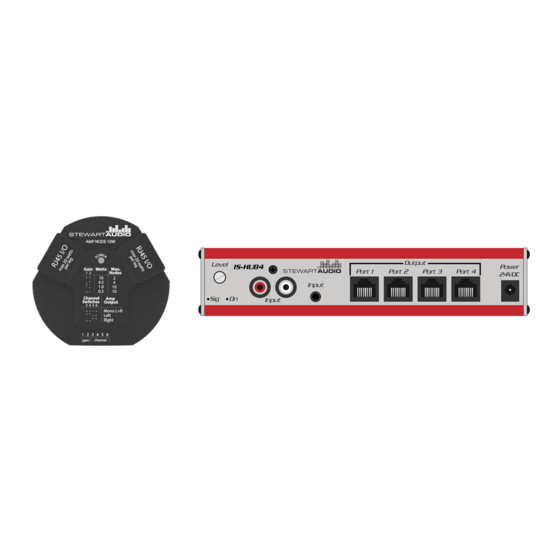
- Page 1 Output Level IS-HUB4 Power Port 1 Port 2 Port 3 Port 4 STEWART AUDIO 24VDC Input Input IntraSound System Owner’s Manual February 2012 www.stewartaudio.com...
-
Page 2: Important Safety Instructions
This amplifier is intended to be operated in a controlled indoor environment. Before using your Stewart Audio Inc. Power Amplifier, please read this Owner’s Manual carefully to ensure optimum trouble-free perfor- 6. -
Page 3: Table Of Contents
2 System Overview ········································································· 6 1.1 Features 3 System Installation ······································································· 8 Your Stewart Audio IntraSound System is the result of years of experience in the design and manufacture of quality amplifiers. As such 4 Operation ······················································································ 12 it provides a combination of performance and operational benefits that simply cannot be found in conventional amplifiers. -
Page 4: System Overview
2 System Overview 2.2 Example System Setup The IntraSound System by Stewart Audio consists of two key com- ponents: the IS-HUB4 and the IS-AmpNode-10. Other components such as Cat5 cable and speakers play a role in the system but will not be the focus of this manual. -
Page 5: System Installation
Each port is capable of outputting a maximum of 20 total watts of pow- Stewart Audio recommends that the unit is secured in some fashion to er to the nodes daisy chained on that port. prevent movement of the unit if one of the cables is pulled during in- stallation of an amplifier node. - Page 6 3.2.1 Node Input Connections Gain Configuration The IntraSound system utilizies Cat5 to send power as well as a stereo signal to each node on the line. For the initial connection between the The gain level on the micro amplifier nodes is adjustable from 0.3W to IS-HUB4 and an IS-AmpNode-10, a Cat5 cable should connect any port 10W using the DIP switches on the front of the unit.
-
Page 7: Operation
Using equipment that is not capable of handling the output wattage may lead to permanent damage. NOTE: Stewart Audio will not be held responsible for damage to your IntraSound System or connected equip- ment if the instructions in this manual are not followed. -
Page 8: Troubleshooting
5 Troubleshooting 6 Technical Specifications Maximum Output 20Hz - 20kHz Problem: Hub’s Power indicator does not turn on. Output per node 10W @ 8Ω Procedure: Check that the hub is plugged into a live outlet. After you Hub’s Total Output Wattage of power supply have ensured that it is not a power issue, check that you have a hot Frequency Response (+0, -3 dB) - Page 9 3-year limited warranty on parts and labor from the date of purchase. In order to be eligible for warranty repairs, If Stewart Audio is unable to contact the sender in 14 days, the mer- the amplifiers and accessories must have been purchased through an chandise will be considered scrap and may be disposed of.
-
Page 10: Accessories
8 Accessories 1. Please write the RA number on three sides of the box. Include the Stewart Audio RA number inside the box and a brief description of the problem. 2. Do not ship any accessories (manuals, cords, hardware, etc.) with your unit.
Need help?
Do you have a question about the IntraSound System and is the answer not in the manual?
Questions and answers