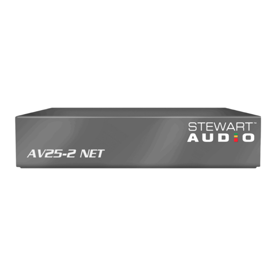
Summary of Contents for Stewart Audio AV25-2 NET Series
- Page 1 AV25-2 NET AV25-2 NET+ AV25-2 NET Series Owner’s Manual December 2014 www.stewartaudio.com...
-
Page 2: Important Safety Instructions
Airflow through the ventilation openings should be Before using your Stewart Audio Inc. Power Amplifier, please read this unobstructed. Owner’s Manual carefully to ensure optimum trouble-free perfor- mance. -
Page 3: Table Of Contents
2.4 Input Connections ······························································ 9 1.1 Features 2.5 Output Connections ·························································· 11 Your Stewart Audio AV Series amplifier is the result of years of 3 Operation ····················································································· 13 experience in the design and manufacture of quality amplifiers. As such 3.1 Operation Precautions ······················································· 13 it provides a combination of performance and operational benefits that 3.2 Controls, Indicators, and Connectors ································... -
Page 4: Setup
2.2.1 Universal-Mount Installation 2 Setup The AV25-2 NET series also has a universal bracket available which al- 2.1 Setup Precautions lows the unit to be mounted against a wall or under a table. Two screws are included in the kit which will affix the bracket to the top or the side of the unit. -
Page 5: Proper Cooling Considerations
When using a balanced input source and connector, you must ensure that the hot, cold, and ground pins of the connector are matched up to the +, -, and ground pins of the AV25-2 NET+’s Phoenix connector re- spectively. Diagrams have been provided for standard XLR and TRS 4.00in... - Page 6 2.4.2 Unbalanced Input Connections Pre-wired unbalanced connectors are available for purchase from Stew- art Audio. These will allow for a quicker installation with less room for error when connecting the CVA Series amplifier to an unbalanced When using an unbalanced input source and connector, a jumper must source.
-
Page 7: Output Connections
NOTE: Stewart Audio will not be held responsible for serving proper polarity. With a small, flat-blade screwdriver, tighten the damage to your AV25-2 NET series amplifier or connect- screw until the leads are held securely in place. Inspect for possible ed equipment if the instructions in this manual are not shorts or broken wires. -
Page 8: Controls, Indicators, And Connectors
3.2 Controls, Indicators, and Connectors AV25-2 NET+ AV25-2 NET LEVEL NETWORK NETWORK PRIORITY #2 LOCAL IN #1 #2 LINE OUT #1 SIG PWR #2 CLIP #1 #2 Speaker #1 #2 LINE OUT #1 SIG PWR #2 Speaker #1 11 12... -
Page 9: Dante
3.2.1 Indicators 3.3 Dante The AV25-2 NET series has up to 4 rear panel LED indicators. The first If you have selected the Dante version of the AV25-2 NET series, con- is the power indicator which will illuminate when power is supplied to figuration is done using the Dante Controller software from Audinate. -
Page 10: Remote Volume Control
GND pin and the MUTE pin. No power should be applied to these pins, simply a contact connection. Q: I do not see the AV25-2 NET series showing up on the network? A: All Stewart Audio products are tagged as Ultimo-<MAC_ADDRESS>... -
Page 11: Troubleshooting
Construction Aluminum Chassis problem. If problem still exists, contact your Authorized Dealer for ser- vice. Dimensions Height 1.25in (3.2cm) Width 6in(15.2cm) Depth 4in (10.2cm) Weight 0.57lbs (0.26kg) Stewart Audio reserves the rate to change features and specifications without notice. -
Page 12: Warranty Information
3-year limited warranty on parts and labor from the data of purchase. In order to be eligible for warranty repairs, If Stewart Audio is unable to contact the sender in 14 days, the mer- the amplifiers and accessories must have been purchased through an chandise will be considered scrap and may be disposed of. -
Page 13: Accessories
The following accessories are available from Stewart Audio for your 1. Please write the RA number on three sides of the box. Include the amplifier. Stewart Audio RA number inside the box and a brief description of the problem. All part numbers shown are Stewart Audio Part Numbers.


Need help?
Do you have a question about the AV25-2 NET Series and is the answer not in the manual?
Questions and answers