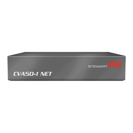
Summary of Contents for Stewart Audio CVA50-1 NET
- Page 1 CVA50-1 NET CVA50-1 NET+ CVA50-1 NET Series Owner’s Manual June 2012 www.stewartaudio.com...
-
Page 2: Important Safety Instructions
Airflow around the unit should be unobstructed. Before using your Stewart Audio Inc. Power Amplifier, please read this Owner’s Manual carefully to ensure optimum trouble-free perfor- This amplifier should not be used near water, for example, near a bathtub, mance. -
Page 3: Table Of Contents
2.2.2 Universal-Mount Installation ·································· 7 1.1 Features 2.2.3 Product Dimensions ·············································· 8 Your Stewart Audio CVA Series amplifier is the result of years of expe- 2.3 Proper Cooling Considerations ··········································· 8 rience in the design and manufacture of quality amplifiers. As such it 2.4 Input Connections ······························································... -
Page 4: Setup
The CVA Series amplifier casing has mount holes on both the top as well as the side of the unit which can be used with the AV-Pole bracket available from Stewart Audio. Two screws are included in the kit which will affix the bracket to the top or side of the unit. -
Page 5: Product Dimensions
See the next two sections for instruc- 1.25in tions on connecting your amplifier to its input source. 3.2cm CVA50-1 NET+ 2.4.1 Balanced Input Connections Front When using a balanced input source and connector, you must ensure that the hot, cold, and ground pins of the connector are matched up to the +, -, and ground pins of the CVA Series’... -
Page 6: Unbalanced Input Connections
2.4.2 Unbalanced Input Connections Pre-wired unbalanced connectors are available for purchase from Stew- art Audio. These will allow for a quicker installation with less room for error when connecting the CVA Series amplifier to an unbalanced When using an unbalanced input source and connector, a jumper must source. -
Page 7: Constant Voltage
100V 70V NOTE: Stewart Audio will not be held responsible for damage to your CVA Series amplifier or connected equip- ment if the instructions in this manual are not followed. -
Page 8: Controls, Indicators, And Connectors
3.2 Controls, Indicators, and Connectors CVA50-1 NET+ CVA50-1 NET LEVEL COBRANET COBRANET 100V 100V PRIORITY PWR CLIP LOCAL IN LINE OUT OUTPUT LINE OUT OUTPUT 10 11 Signal Present Indicator LED Power Indicator LED Signal Priority Switch CobraNet Connector CobraNet Connector... -
Page 9: Cobranet
Q: What submap channels do the CVA50-1 NET+ use? 3.3 CobraNet A: Since the CVA50-1 NET+ is a 2-channel device, only the first two 3.3.1 CobraNet FAQ submap channels are valid (channels 1 and 2). Data sent on channels 3- 8 will be ignored. -
Page 10: Troubleshooting
Rx #1 and Rx #2 directly correspond to Channel 1 and Channel 2 of the 4 Troubleshooting amplifier. Problem: Power indicator does not turn on. Procedure: Check that the unit’s power supply is plugged into a func- tioning outlet and the power supply is correctly connected to the unit. Ensure that there is an audio signal present on the audio input indicated by the green LED being lit. -
Page 11: Technical Specifications
This section includes the return procedures which must be followed in order to prevent processing delay or cost to the customer. Please read the entire section before contacting Stewart Audio for returns. Stewart Audio reserves the rate to change features and specifications without notice. -
Page 12: Return Authorization
2. Do not ship any accessories (manuals, cords, hardware, etc.) with your unit. These items are not needed to service your product. If Stewart Audio is unable to contact the sender in 14 days, the mer- Stewart Audio will not be held responsible for these items if they chandise will be considered scrap and may be disposed of. -
Page 13: Accessories
8 Notes 7 Accessories The following accessories are available from Stewart Audio for your amplifier. All part numbers shown are Stewart Audio Part Numbers. Mounting Brackets AV-POLE Pole-mount bracket for AV Series amplifiers AV-BRACKET Universal mounting bracket for AV Series amplifiers...


Need help?
Do you have a question about the CVA50-1 NET and is the answer not in the manual?
Questions and answers