Grizzly G1030 Owner's Manual
Grizzly dust collector user manual
Hide thumbs
Also See for G1030:
- Instruction manual (26 pages) ,
- Parts list (3 pages) ,
- Owner's manual (36 pages)
Table of Contents
Advertisement
Quick Links
Download this manual
See also:
Instruction Manual
Advertisement
Table of Contents

Related Manuals for Grizzly G1030


Summary of Contents for Grizzly G1030
- Page 1 MODEL G1030 DUST COLLECTOR OWNER'S MANUAL WARNING: NO PORTION OF THIS MANUAL MAY BE REPRODUCED IN ANY SHAPE OR FORM WITHOUT THE WRITTEN APPROVAL OF GRIZZLY INDUSTRIAL, INC.
-
Page 3: Table Of Contents
Table of Contents INTRODUCTION ... 2 SECTION 1: SAFETY ... 5 SECTION 2: CIRCUIT REQUIREMENTS ... 8 SECTION 3: SETUP ... 9 SECTION 4: DESIGNING THE SYSTEM ... 14 SECTION 5: OPERATIONS ... 22 SECTION 6: ACCESSORIES ... 23 SECTION 7: MAINTENANCE... 25 SECTION 8: SERVICE ... -
Page 4: Introduction
INTRODUCTION Manual Accuracy Contact Info your machine may not exactly match the manual Machine Description www.grizzly.com... -
Page 5: Machine Data Sheet
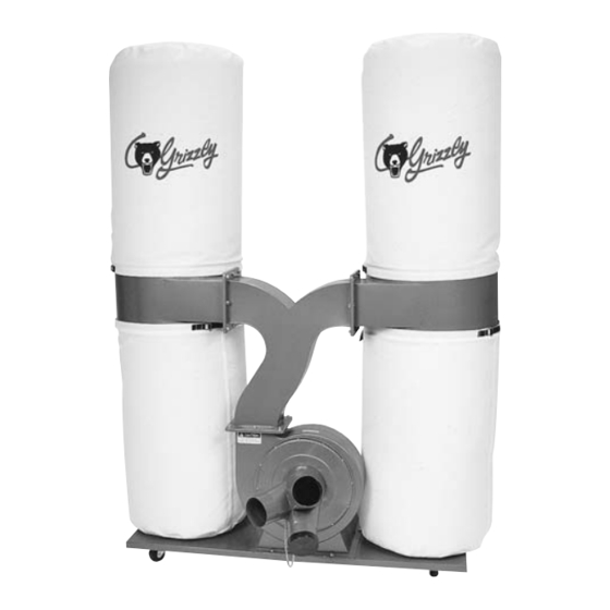
Machine Data Sheet Customer Service #: (570) 546-9663 · To Order Call: (800) 523-4777 · Fax #: (800) 438-5901 MODEL G1030 3 HP DUST COLLECTOR Weight... 156 lbs. Length/Width/Height... 49-1/2 x 21-1/2 x 78 in. Foot Print (Length/Width)... 49-1/2 x 21-1/2 in. - Page 6 No Of Upper Bags...2 Upper Bag Cap...5.7 cu. ft. Lower Bag Cap...5.7 cu. ft. No Of Lower Bags...2 Upper Bags Total Area...11.4 cu. ft. Lower Bags Total Area...11.4 cu. ft. Upper Bag Diameter...19 in. Upper Bag Length... 33 in. Lower Bag Diameter...19 in. Lower Bag Length...
-
Page 7: Section 1: Safety
SECTION 1: SAFETY For Your Own Safety, Read Instruction Manual Before Operating this Machine The purpose of safety symbols is to attract your attention to possible hazardous conditions. This manual uses a series of symbols and signal words intended to convey the level of importance of the safety messages. -
Page 8: Safety Instructions For Machinery
Safety Instructions for Machinery 7. ONLY ALLOW TRAINED AND PROP- ERLY SUPERVISED PERSONNEL TO OPERATE MACHINERY. 8. KEEP CHILDREN/VISITORS 9. UNATTENDED OPERATION. 10. DO DANGEROUS ENVIRONMENTS. 11. KEEP WORK AREA CLEAN AND WELL LIGHTED. 12. USE A GROUNDED POWER SUPPLY RATED FOR THE MACHINE AMPERAGE. -
Page 9: Additional Safety For Dust Collectors
Additional Safety for Dust Collectors MACHINE USE. KEEPING FINGERS SAFE. SAFE SERVICING. SUSPENDED DUST PARTICLES AND IGNITION SOURCES EMPTYING DUST. Like all machines there is danger associated with this machine. Accidents are frequently caused by lack of familiarity or failure to pay attention. -
Page 10: Section 2: Circuit Requirements
SECTION 2: CIRCUIT REQUIREMENTS 220V Single-Phase Operation Serious personal injury could occur if you connect the machine to power before com- pleting the setup process. DO NOT connect the machine to the power until instructed later in this manual. Electrocution or fire could result if machine is not grounded and installed in compliance with electrical... -
Page 11: Section 3: Setup
SECTION 3: SETUP This machine presents serious injury hazards to untrained users. Read through this entire manu- al to become familiar with the controls and opera- tions before starting the machine! Wear safety glasses dur- ing the entire setup pro- cess! This machine and its com- ponents are very heavy. -
Page 12: Site Considerations
Inventory Note: If you can't find an item on this list, check the mounting location on the machine or examine the packaging materials carefully. Occasionally we pre-install certain components for shipping purposes. Inventory: Site Considerations Floor Load Machine Data Sheet Placement Location Figure 2. - Page 13 Assembly To assemble your machine: Figure 3. Figure 3. Figure 4. Figure 4. Figure 5. Note: When connecting parts that have a gasket between them, always tighten the fasteners in a crisscross manner to ensure the gasket does not become crimped and the seal compromised.
- Page 14 Figure 7. Figure 8. Note: The collector attaches to each sup- port bracket. The inside of the collector is funnel shaped and directs the air around in a cyclone motion. Make sure that the inside taper (funnel) is faced downward and the col- lector inlet faces toward the collector body.
-
Page 15: Test Run
Step 8 Note: DO NOT force the clamp, if it is too tight, choose the next notch over, then clamp in place. Figure 11. Test Run Figure Troubleshooting To test run the machine: Do NOT put hands or small objects near inlet openings during opera- tion. -
Page 16: Section 4: Designing The System
SECTION 4: DESIGNING THE SYSTEM Duct Material General Always guard against static electrical build up by grounding all dust col- lection lines. Metal Duct Dust Collection Basics. Figure 12. - Page 17 Flexible Duct Plastic Duct Figure 14. Figure 13.
-
Page 18: System Design
System Design Step 1. Decide Who Will Design Step 2. Sketch Your Shop Layout Workshop Planner www.grizzly.com Workshop Planner Note: After you're finished, make sure to save your layout for later modification. Figure 15 Figure 15. Step 3. Sketch a Basic Duct Layout Figure 16. -
Page 19: Step 4. Determine Required Cfm Of Each Machine
Figure 19 Machine Average Dust Port Size Step 4. Determine Required CFM of Each Machine Figure 18 Figure 19. Figure 20 Machine Approximate Dust Port Size Required CFM Figure 20. Figure 18. -
Page 20: Determining Branch Line Duct Size
Determining Main Line Duct Size Figure 21 Figure 21. Determining Branch Line Duct Size Note: Systems with powerful dust collectors work better if multiple blast gates are left open. This also allows you to run two machines at once. Experiment with different combinations of blast gates open/closed to find the best results for your system. -
Page 21: Calculating Duct Resistance
Calculating Duct Resistance Duct Approximate Dia. Static Pressure Static Pressure Loss Per Foot of Loss Per Foot Rigid Pipe Fitting 90˚ 45˚ Dia. Elbow Elbow Wye(Y) Figure 24. To calculate the static pressure of any given line in the system, follow these steps: Figure 24 Additional Factors Approximate... -
Page 22: System Grounding
Note: When calculating static pressure loss to determine if multiple lines can be left open at the same time, only include the main line numbers once. System Grounding Page 23 Always guard against static electrical build up by grounding all dust collection lines. - Page 23 Figure 27 Figure 28. Figure 28. Figure 27.
-
Page 24: Section 5: Operations
OMMEND that you read books, trade maga- zines, or get formal training before begin- ning any projects. Regardless of the con- tent in this section, Grizzly Industrial will not be held liable for accidents caused by lack of training. this... -
Page 25: Section 6: Accessories
SECTION 6: ACCESSORIES T20514—Small Half-Mask Respirator T20515—Medium Half-Mask Respirator T20516—Large Half-Mask Respirator T20511—Pre-Filter P100 T20539—Cartridge Filter 2PK P100 T20541—Cartridge Filter 2PK P100 & O Vapor Figure 29. H5293—4" Metal Duct Starter Kit H5295—5" Metal Duct Starter Kit H5297—6" Metal Duct Starter Kit Figure 30. - Page 26 H7216—5" x 5' Rigid Metal Flex Hose H7217—6" x 5' Rigid Metal Flex Hose H7218—7" x 5' Rigid Metal Flex Hose H7219—8" x 5' Rigid Metal Flex Hose Figure 34. G4996—Bottom Bag For G1030 G1027—Top Bag For G1030 Figure 35.
-
Page 27: Section 7: Maintenance
Failure to do this may result in serious person- al injury. Schedule Daily Check: Lubrication Always wear a respira- tor when emptying the dust collection bags on the dust collector. Sawdust may cause allergic reactions or respiratory problems. Bag Cleaning we strongly rec- ommend... -
Page 28: Section 8: Service
SECTION 8: SERVICE Troubleshooting Motor & Electrical... -
Page 29: Dust Collector Operation
Dust Collector Operation System Design Page 16 System Design Page 16... -
Page 30: Wiring Diagram
The motor wiring shown here is current at the time of printing, but it match your machine. Always use the wiring diagram inside the motor junction box. View this page in color at www.grizzly.com. 220 VAC L6-20 PLUG (as recommended) -
Page 31: Parts Breakdown
Parts Breakdown... -
Page 32: Parts List
REF PART # DESCRIPTION P1028001 CASTER PFB01 FLANGE BOLT 5/16"-18 X 1/2" P1030Z2003 BASE PLATE V2.01.09 PS06 PHLP HD SCREW 10-24 X 3/8" P1030005 INLET COVER PSB121M CAP SCREW M6-1 X 20 (LH) PB09 HEX BOLT 5/16"-18 X 1/2" P1028009 SPECIAL WASHER P1029010 TURBO FAN... -
Page 33: Warranty Card
The following information is given on a voluntary basis. It will be used for marketing purposes to help us develop better products and services. Of course, all information is strictly confidential. Note: We never use names more than 3 times. _____________________________________________________________________ _________________________________________________________________________________ _________________________________________________________________________________... -
Page 35: Warranty And Returns
WARRANTY AND RETURNS... - Page 36 ® Buy Direct and Save with Grizzly – Trusted, Proven and a Great Value! ~Since 1983~ Visit Our Website Today For Current Specials! ORDER 24 HOURS A DAY! 1-800-523-4777...
Need help?
Do you have a question about the G1030 and is the answer not in the manual?
Questions and answers