Table of Contents
Advertisement
Quick Links
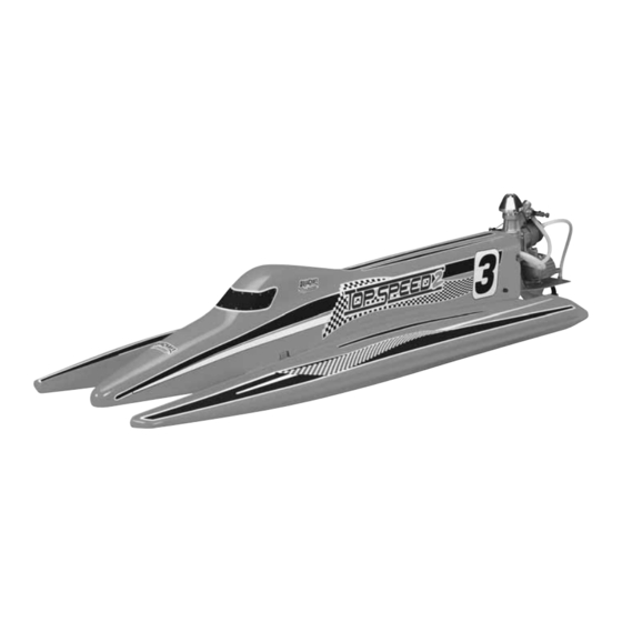
ASSEMBLY AND OPERATION MANUAL
ARR:
HCAB5010 – White
HCAB5011 – Yellow
HCAB5012 – Red
AquaCraft™ will warrant this kit for 90 days after the purchase from defects in materials or
workmanship. AquaCraft will either repair or replace, at no charge, the incorrectly made part.
Make sure you save the receipt or invoice you were given when you bought your model! It is your
proof of purchase and we must see it before we can honor the warranty.
To return your Top Speed 2 for repairs covered under warranty you should send your boat to:
Entire Contents © Copyright 2005
3002 N. Apollo Drive, Suite 1
Champaign, Illinois 61822
Attn: Service Department
Phone: (217) 398-0007, 9:00 am – 5:00 pm Central Time M-F
E-mail: hobbyservices@hobbico.com
Warranty
Hobby Services
™
HCAZ3026 for HCAB5010/5011/5012 V1.1
Advertisement
Table of Contents

Subscribe to Our Youtube Channel
Related Manuals for AquaCraft Top Speed 2 HCAB5010


Summary of Contents for AquaCraft Top Speed 2 HCAB5010
- Page 1 HCAB5012 – Red Warranty AquaCraft™ will warrant this kit for 90 days after the purchase from defects in materials or workmanship. AquaCraft will either repair or replace, at no charge, the incorrectly made part. Make sure you save the receipt or invoice you were given when you bought your model! It is your proof of purchase and we must see it before we can honor the warranty.
-
Page 2: Table Of Contents
USEFUL TOOLBOX ITEMS ..........3 and racing. If you have any questions regarding assembly, OTHER USEFUL ITEMS TO HAVE ON HAND ....3 be sure to call the AquaCraft Product Support staff at: ITEMS REQUIRED TO COMPLETE ASSEMBLY ....3 BOAT TERMINOLOGY ............3 (217) 398-8970 SCREW INFORMATION ............3... -
Page 3: Specifications & Description Changes
❏ instruction manual are subject to change without notice. O.S. ® .21 XM Engine (OSMG1721) ❏ AquaCraft maintains no responsibility for inadvertent errors Futaba ® 2PL 2-channel radio (FUTK01**) ❏ in this manual. Drill bits: 1/8" [3mm], 13/64" [5mm] (or 7/32" [5.5mm]), 15/64"... -
Page 4: Helpful Hints
If any parts are missing or are not of acceptable quality, or if you need assistance with assembly, contact Product Support. When reporting defective or missing parts, use the part names exactly as they are written in the Kit Contents list. Aquacraft Product Support: 3002 N. Apollo Drive, Suite 1 Champaign, IL 61822 Telephone: (217) 398-8970, ext. -
Page 5: Final Assembly Instructions
FINAL ASSEMBLY INSTRUCTIONS REMOVE THE CANOPY Carefully remove your Top Speed 2 and stand from the box. Carefully remove all remaining parts bags from the box. You may wish to keep the box in order to more easily transport and store your Top Speed 2. Decals have been provided for your Top Speed 2. - Page 6 ❏ ❏ 1. Use a Phillips head screwdriver to remove the two (2) 3. Slide the mounting plate out of the swivel brackets and 3 x 10mm screws holding the steering arm to the upper invert the mounting plate as shown. Be certain to replace swivel bracket as shown.
- Page 7 [3mm] above the set up board. The prop thrust angle should be parallel to the surface of the set-up board (0° thrust). Once the desired position is attained, tighten the 6-32 socket head cap screws firmly. Use thread-locking compound and be careful not to overtighten them. Note: You will want to check thrust angle and prop depth after all of the assembly steps have been completed and again before running the Top Speed 2.
-
Page 8: Prepare The Radio Box
*TIP: A body reamer can be used instead. Just be sure to PREPARE THE RADIO BOX check the size of the hole often and be careful not to make the opening too large. If using a drill bit, be careful not to “blow”... -
Page 9: Install The Steering & Throttle Servos
INSTALL THE STEERING & THROTTLE SERVOS ❏ 1. Cut two X-shaped servo arms down to the configuration shown above. Note that the lengths of the remaining arms have also been decreased by one hole. ❏ 7. Put a bead of CA glue on the rubber throttle pushrod seal and insert it in the radio box as shown. -
Page 10: Install The Remaining Radio Gear
INSTALL THE REMAINING RADIO GEAR It is a good idea at this point to install the rest of your radio gear. ❏ 4. Insert the antenna tube into the rubber antenna exit and thread the antenna up through the tube as shown. ❏... - Page 11 ❏ 6. Locate two (2) screw-lock pushrod connectors. One ❏ 3. Make sure the engine is neutral (use the stand to hold will attach to the arm of the throttle servo and the other will the engine straight) and use a felt-tip pen to make a mark attach to the throttle arm of the engine as shown.
-
Page 12: Install The Fuel Tank
secure it by tightening the socket head screw (3/32" ATTACH THE COWL [2.5mm]) as shown. Cut off the excess after making sure that there is enough throttle cable to allow the engine to move freely. PLEASE NOTE: You will need to do four things before you can attach the cowling. -
Page 13: Check The Radio System
chin to create a balance point for running the O.S. 21 XM or the K&B 3.5SS/K&B 3.5 SX. This balance point is 9-1/2" [241mm] from the back of the sponsons. *The Thunder Tigre 3.5 Outboard weighs more than the other engines and may require additional weight. Modified Engines: Achieving the proper balance with a modified engine required applying 3-5 ounces of weight. -
Page 14: Propeller Information
PROPELLER THRUST ANGLE PROPELLER INFORMATION PROPELLER SELECTION The Top Speed 2 has been tested with many engine/propeller combinations. A balanced Octura Models X440 has worked well with both stock and modified engines. Octura Models X-Series provides an extensive selection of propellers. In the Octura prop series, the last two numbers indicate the diameter in millimeters. -
Page 15: Running The Top Speed 2
PROPELLER DEPTH RUNNING THE TOP SPEED 2 The depth of the propeller has an influence on both engine performance and boat handling characteristics. Running the LAUNCH PROCEDURE engine with the center line of the prop shaft above the bottom ❏ running surface of the sponsons produces less “load”... -
Page 16: Racing
Gently pull the rubber drain plug located on the transom and different from running alone and water conditions constantly allow any water that may have found a way inside the hull to change during a race. Five or six boats racing against one drain out. -
Page 17: Performance Tips
All three national organizations offer both stock and courses any way you desire, using your imagination to modified engine classes for tunnel hulls like the Top Speed make the races more interesting. Usually the smaller 2. Participation by those new to the hobby of model boating courses will provide more action and excitement. - Page 18 Top Speed 2 and increase OTHER ITEMS AVAILABLE FROM the chances of capsizing. AQUACRAFT • Total run time of the Top Speed 2 is approximately 10-12 minutes (assuming you begin with a full tank of fuel).
-
Page 19: Ordering Replacement Parts
ORDERING REPLACEMENT PARTS To order replacement parts for the AquaCraft Top Speed 2, use the order numbers in the Replacement Parts List that follows. Replacement parts are available only as listed and can be purchased from hobby shops or mail order/ Internet order firms.
Need help?
Do you have a question about the Top Speed 2 HCAB5010 and is the answer not in the manual?
Questions and answers