LeMond REvMaster Owner's Manual
Hide thumbs
Also See for REvMaster:
- Owner's manual (27 pages) ,
- Assembly instructions manual (15 pages) ,
- Brochure (3 pages)
Table of Contents
Advertisement
Advertisement
Table of Contents

Related Manuals for LeMond REvMaster


Summary of Contents for LeMond REvMaster
- Page 1 Owner's Manual...
- Page 2 LeMond Fitness Inc. 17820 Woodinville-Redmond Rd. Building B, Suite 888 Tel.: (425) 482-6773 Fax: (425) 482-6724 Visit our website at www.LeMondfitness.com P/N 300202 © 2002 LeMond Fitness Inc. LeMond and RevMaster are registered trademarks. Page iii...
- Page 3 RevMaster exercise bike is warranted by LeMond Fitness Inc. to be free of all defects in materials and workmanship. This warranty does not apply to any defect caused by negligence, misuse, accident, alteration, improper maintenance, or an “act of God.”...
- Page 4 The LeMond RevMaster bike was designed by Paul Swift under the direction of Greg LeMond. LeMond is the first American to win the Tour de France. A cyclist who has won the world's most challenging races, Greg LeMond has also revolutionized the sport by introducing cutting edge technology that is commonplace today.
-
Page 5: Table Of Contents
CONTENTS SAFETY GUIDELINES ............1 INSTALLATION INSTRUCTIONS ........3 Delivery ................3 GUIDELINES FOR SAFE OPERATION ......7 BASIC OPERATING INSTRUCTIONS ......8 Your first workout on the LeMond RevMaster ® ® Exercise Bike ..............8 Seat Adjustment ............. 8 Handlebar Adjustment ........... - Page 6 Figure 7: Brake Tension Knob Assembly ...... 30 Figure 8: Brake Pad Assembly ........31 Figure 9: V-Plunger & Plug ........... 32 SPECIFICATIONS ..............33 LIST OF TABLES Table 1. Dimensions and Specifications for the LeMond RevMaster Exercise Bike ......3 ® ® Page vii...
-
Page 7: Safety Guidelines
4. Rotate the tension knob clockwise to apply resistance to the flywheel prior to standing on the pedals. 5. Do not dismount the RevMaster bike until both of the pedals and the flywheel are at a complete stop. 6. Never turn the pedal crank arms by hand. Do not expose your hands or your arms to the drive mechanism as possible injury could occur. - Page 8 Failure to follow all guidelines may compromise the effectiveness of the exercise experience, expose yourself (and possibly others) to injury, and reduce the longevity of the equipment. SAVE THESE INSTRUCTIONS Your comments and suggestions are welcome. Congratulations, and thank you for buying the RevMaster! Your serial number(s):___________________________________________ ___________________________________________________________ ___________________________________________________________...
-
Page 9: Installation Instructions
116 pounds (53 kg) DELIVERY Your LeMond RevMaster will arrive packed in 1 carton. Upon arrival fully inspect the carton for damage. Point out any damage to the delivery person and have the delivery person record the damage on the delivery paperwork. - Page 10 INSTALLATION INSTRUCTIONS Seat Handlebar Post Pedals 4x Mounting Bolts Water Bottle Cage 3x Hex Keys Wrench Tool 4x Handles Seat Post Rear Base Handlebar Assembly Front Base B . Assemble the Bike 5. With the help of an assistant, lift the bike up and off the pallet. 6.
- Page 11 INSTALLATION INSTRUCTIONS 7. The handlebar post is the post that has a smooth finish, and no groove on top. Insert the handlebar post into the handlebar tube. Loosely thread a handle without a washer into the main frame. Raise the handlebar post to the desired height and tighten the handle to secure the handlebar post.
- Page 12 INSTALLATION INSTRUCTIONS 11. Position the seat with seat slider over the seat post. Loosely thread a handle with a washer through the seat post into the seat slider. Slide the seat to the desired position and tighten the handle. 12. The pedals are marked as if you are seated on the bike, "R" for right, and "L"...
-
Page 13: Guidelines For Safe Operation
5. Although all equipment manufactured by LeMond Fitness, Inc. has ®... -
Page 14: Basic Operating Instructions
™ EXERCISE SYSTEM Basic Instructions for First-Time Users 1. Properly fit the bike to your body type. The RevMaster offers up/ down and fore/aft adjustments that are clearly marked to ensure a quick and easy custom fit for each workout. -
Page 15: Pedal Strap Adjustment
BASIC OPERATING INSTRUCTIONS position mark on the handlebar stem for future reference. 2. Adjust the handlebar fore or aft by rotating the handlebar adjust- ment handle counter clockwise and sliding the handlebar forward or backward as desired. Note the final position mark on the handlebar for future reference. -
Page 16: General Exercise Guidelines
GENERAL EXERCISE GUIDELINES SETTING A GOAL The first step to a successful exercise program is to set realistic goals and objectives. Are you wanting an exercise program that is geared to build muscle, maintain muscle tone, or lose weight? In order to ensure that you fully receive all the benefits of a sound exercise program, you need to first identify the existence (if any) of risk factors that may influence the design of your exercise program. -
Page 17: Exercise Principles
GENERAL EXERCISE GUIDELINES •Duration - 10-30 seconds for each stretch •Repetitions - 2-6 for each stretch •Type - static, with a major emphasis on the low back and hamstrings area because of the high preva- lence of low-back pain syndrome in our society. EXERCISE PRINCIPLES* The American College of Sports Medicine has developed a position paper concerning exercise programs for healthy adults and the need for guide-... -
Page 18: Maintenance Instructions
MAINTENANCE INSTRUCTIONS HELPFUL HINTS The safety level given by the design of this equipment can only be maintained when the equipment is regularly examined for damage and wear. Inoperable components should be replaced immediately or the equipment should be put out of use until it is repaired. Read all mainte- nance instructions thoroughly before beginning work. -
Page 19: Daily
MAINTENANCE INSTRUCTIONS Daily 1. Wipe down the LeMond RevMaster after each use to remove ® ™ sweat and moisture. Use soap and water, or a diluted non-abrasive cleaner solution. Rinse to remove detergent residue and then dry. 2. If your bikes are used frequently in group exercise sessions, inspect for loose pedals prior to starting any class. -
Page 20: Troubleshooting
TROUBLESHOOTING This section outlines tests to systematically identify and isolate the cause of common problems. The first step is to identify the problem. Once you have identified the problem, perform the tests in exactly the same order as written. Refer to the appropriate "Parts Removal and Replacement" section of this manual for all disassembly and assembly instructions. -
Page 21: Parts Removal And Replacement
PARTS REMOVAL AND REPLACEMENT ADJUSTMENT HANDLES Handlebar/Seat post adjustment handle 1. Support the post with one hand and rotate the adjustment handle counterclockwise with your other hand until the handle is un- threaded from the frame. 2. Lower the post so that it rests on the frame. 3. -
Page 22: Belt
PARTS REMOVAL AND REPLACEMENT BELT Belt Tensioner Screw 1. Remove the front cover. Shoulder bolt 2. Loosen the shoulder bolt with an adjustable wrench. 3. Use the allen wrench to loosen the belt tensioner screw located on top of the idler tension bearings. - Page 23 PARTS REMOVAL AND REPLACEMENT the bearing cup – rotate the bottom bracket tool an addi- tional 10 degrees clockwise. 8. Verify that the bottom bracket spindle is not loose by tugging on the spindle shaft. 9. Use the lock ring removal tool to tighten the lock ring.
-
Page 24: Brake Pad Assembly
PARTS REMOVAL AND REPLACEMENT BRAKE PAD ASSEMBLY 1. Turn the tension knob counter- clock wise to remove tension on the brake pad assembly. 2. Remove the brake pad mount- ing nut and screw from the brake pad spring using a 10- mm wrench and 4-mm allen wrench. -
Page 25: Covers
PARTS REMOVAL AND REPLACEMENT COVERS Front Cover 1. Using the screwdriver remove the four screws that secure the cover to the frame and back cover. 2. Slide the cover over the right pedal crank and remove the cover from the frame. Back Cover 1. -
Page 26: Handlebar
PARTS REMOVAL AND REPLACEMENT 5. Use a 4 mm allen wrench to remove the pulley from the flywheel. 6. Pull the right pillow block bearing off the flywheel shaft. 7. Flip the flywheel over on the floor. 8. Pull the left pillow block bearing off the flywheel shaft. 9. -
Page 27: Pedals
PARTS REMOVAL AND REPLACEMENT post in the desired location and rotate the handlebar post adjustment handle clockwise to secure the handlebar post. Note: If the post will not slide all the way down you will need to push the V- plunger back inside the frame tube. 7. -
Page 28: Seat
PARTS REMOVAL AND REPLACEMENT Right Crank Arm 1. Remove the front cover and belt. 2. Using an 8-mm wrench, remove the crank arm bolt. 3. Thread a bicycle crank arm removal tool onto the crank arm shaft . 4. As you tighten the crank arm removal tool on the shaft, the crank arm will pull off the crank arm shaft. -
Page 29: Seat Post
FIGURES handle clockwise to secure the seat. 6. Ensure that the handle does not stick out to the right or left. Each handle is spring loaded so that you can properly align the frame and the handle. Simply pull out on the handle and rotate it for correct alignment. -
Page 30: Figure 1: Final Assembly
FIGURES Figure 1: Final Assembly Page 24... -
Page 31: Figure 2: Crank Assembly
FIGURES Figure 2: Crank Assembly Page 25... -
Page 32: Figure 3: Flywheel Assembly
FIGURES Figure 3: Flywheel Assembly Page 26... -
Page 33: Figure 4: Belt Tension
FIGURES Figure 4: Belt Tension Page 27... -
Page 34: Figure 5: Front Base Assembly
FIGURES Figure 5: Front Base Assembly Page 28... -
Page 35: Figure 6: Rear Base Assembly
FIGURES Figure 6: Rear Base Assembly Page 29... -
Page 36: Figure 7: Brake Tension Knob Assembly
FIGURES Figure 7: Brake Tension Knob Assembly Page 30... -
Page 37: Figure 8: Brake Pad Assembly
FIGURES Figure 8: Brake Pad Assembly Page 31... -
Page 38: Figure 9: V-Plunger & Plug
FIGURES Figure 9: V-Plunger & Plug Page 32... -
Page 39: Specifications
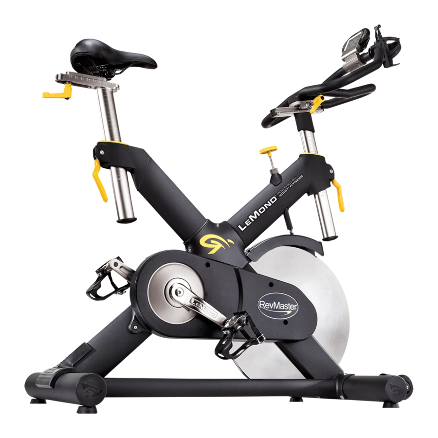
SPECIFICATIONS A - Frame: •Ultra-strong, X-Style Design •Welded frame and bolted base •Stainless steel components •22 inch wide base with extra large diameter adjustable levelers B - Flywheel: •47-pound precision-machined, chrome-plated flywheel •Machined stainless steel axle C - Braking and resistance mechanism: •Turn-knob design for tension;... - Page 40 SPECIFICATIONS G - Seat: •Stainless steel dual position seat slider adjusts fore/aft •Unique V-clamp and rotated tube design for enhanced stability •Adjustment marks for up/down and fore/aft •Stainless steel post adjusts up/down H - Transport Wheels: •Extra large in-line skate wheels •Wheel brackets are welded to the frame I - Drive Train: •Non-slip, durable belt...
Need help?
Do you have a question about the REvMaster and is the answer not in the manual?
Questions and answers