Axel Oxygen 5 User Manual
Modular mixing console
Hide thumbs
Also See for Oxygen 5:
- User manual (137 pages) ,
- User manual (124 pages) ,
- Operating manual (46 pages)
Table of Contents
Advertisement
Advertisement
Table of Contents

Related Manuals for Axel Oxygen 5


Summary of Contents for Axel Oxygen 5
- Page 1 Oxygen 5 User Manual Modular mixing console (Rev. 4.0 ENG)
-
Page 2: Table Of Contents
OXYGEN 5 SERIES INTRODUCTION CONTENT OXYGEN 5 SERIES INTRODUCTION ........................4 OXYGEN 5 – AVAILABLE FRAME SIZE ......................4 OXYGEN 5 – AVAILABLE MODULES ......................... 5 THIS MANUAL ..............................6 AVAILABLE FRAME SIZE PICTURES ........................ 7 SAFETY WARNINGS / ISTRUZIONI PER LA SICUREZZA ..................8 FOREWORD ............................... - Page 3 APPENDIX F – BALANCED AUDIO CONNECTION JACK - JACK ..............58 20.6 APPENDIX F – MODULE CONNECTION ......................59 20.7 TECHNICAL SPECIFICATIONS ........................... 60 WARRANTY ................................. 61 WEEE Directive – Informativa RAEE ......................... 62 WARRANTY ................................. 63 DECLARATION OF ROHS CONFORMITY ......................63 AXEL TECHNOLOGY IN TOUCH ........................64...
-
Page 4: Oxygen 5 Series Introduction
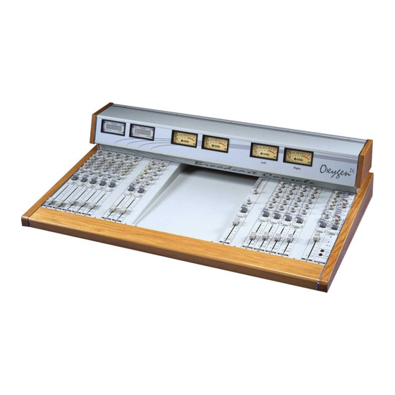
1.1 OXYGEN 5 – AVAILABLE FRAME SIZE Oxygen 5 console is available in two frame sizes: the frame 18, which can contain 18 overall modules, and the frame 26. A script try (10 module wide) can be fitted for both versions. The frames are inox steel + aluminium made, with wood finishing touch. -
Page 5: Oxygen 5 - Available Modules
OXYGEN 5 SERIES INTRODUCTION 1.2 OXYGEN 5 – AVAILABLE MODULES CODE# MODEL DESCRIPTION A103050100 OX5-MONO Mono (Micro/Line) module, VCA control, External control port for remote module control, without tone controls A103050310 OX5-MONO-EQ Tone section for Mono Module A103050110 OX5-ST-L/L Stereo (Line/Line) module, VCA control, External... -
Page 6: This Manual
OXYGEN 5 SERIES INTRODUCTION 1.3 THIS MANUAL This User Manual has been developed for Oxygen 5 Frame 18 and Oxygen 5 Frame 26 size. Some features can be changed without notice. -
Page 7: Available Frame Size Pictures
OXYGEN 5 SERIES INTRODUCTION 1.4 AVAILABLE FRAME SIZE PICTURES A103050010 OX5-FR18 OXYGEN 5 Professional Broadcast modular console frame 16 Frame size 18 Channel IN +1, Master/Monitor, 2Vu, External Power Supply Unit 230/115Vac. A103050011 OX5-FR26 OXYGEN 5 Professional Broadcast modular console frame 24... -
Page 8: Safety Warnings / Istruzioni Per La Sicurezza
SAFETY WARNINGS / ISTRUZIONI PER LA SICUREZZA 1 SAFETY WARNINGS / ISTRUZIONI PER LA SICUREZZA SAFETY WARNINGS CONSIGNES DE SÉCURITÉ IMPORTANTES ISTRUZIONI IMPORTANTI PER LA SICUREZZA WICHTIGE SICHERHEITSHINWEISE INSTRUCCIONES IMPORTANTES DE SEGURIDAD (Rel. 2.0) 1.1 FOREWORD For your own safety and to avoid invalidation of the warranty all text marked with these Warning Symbols should be read carefully. -
Page 9: Safety Warnings
SAFETY WARNINGS 2 SAFETY WARNINGS The installation and servicing instructions in this manual are for use by qualified personnel only. - Read All Instructions. All safety and operating instructions must be read before operating the product. They also must be retained for future reference, as it contains a number of useful hints for determining the best combination of equipment settings for Yr particular application. -
Page 10: Consignes De Sécurité Importantes
CONSIGNES DE SÉCURITÉ IMPORTANTES CONSIGNES DE SÉCURITÉ IMPORTANTES - Lire ces consignes - Conserver ces consignes - Observer tous les avertissements - Suivre toutes les consignes - Ne pas utiliser cet appareil à proximité de l’eau - Ne pas obstruer les ouvertures de ventilation. Installer en respectant les consignes du fabricant - Ne pas installer à... -
Page 11: Istruzioni Importanti Per La Sicurezza
ISTRUZIONI IMPORTANTI PER LA SICUREZZA 4 ISTRUZIONI IMPORTANTI PER LA SICUREZZA - Leggere le presenti istruzioni - Conservare queste istruzioni - Osservare tutte le avvertenze - Seguire scrupolosamente tutte le istruzioni - Non usare questo apparecchio in prossimità di acqua - Non ostruire alcuna apertura per il raffreddamento. -
Page 12: Wichtige Sicherheitshinweise
WICHTIGE SICHERHEITSHINWEISE 5 WICHTIGE SICHERHEITSHINWEISE - Diese Hinweise LESEN - Diese Hinweise AUFHEBEN - Alle Warnhinweise BEACHTEN - Alle Anweisungen BEFOLGEN - Dieses Gerät NICHT in der Nähe von Wasser verwenden - KEINE Lüftungsöffnungen verdecken. Gemäß den Anweisungen des Herstellers einbauen - Nicht in der Nähe von Wärmequellen, wie Heizkörpern, Raumheizungen, Herden oder anderen Geräten (einschließlich Verstärkern) installieren, die Wärme erzeugen - Die Schutzfunktion des Schukosteckers NICHT umgehen. - Page 13 WICHTIGE SICHERHEITSHINWEISE Inpoliger Netzschalter. In Notfälle oder für Wartungsarbeiten Netzkabel trennen. Der Netzstecker fungiert auch als Trennelement muss deshalb zugänglich bleiben...
-
Page 14: Instrucciones Importantes De Seguridad
INSTRUCCIONES IMPORTANTES DE SEGURIDAD 6 INSTRUCCIONES IMPORTANTES DE SEGURIDAD - LEA estas instrucciones - CONSERVE estas instrucciones - PRESTE ATENCION a todas las advertencias. - SIGA todas las instrucciones - NO utilice este aparato cerca del agua - NO obstruya ninguna de las aberturas de ventilación.Instálese según lo indicado en las instrucciones del fabricante - No instale el aparato cerca de fuentes de calor tales como radiadores, registros de calefacción, estufas u otros aparatos (incluyendo amplificadores) que produzcan calor... - Page 15 INSTRUCCIONES IMPORTANTES DE SEGURIDAD El interruptor de alimentación es unipolar. En el caso de peligro, desconecte el cable de alimentación. Porque la clavija de conexion a red sirve por la desconection de la unidad, la clavija debe ser ubicada en proximidad de la unidad...
-
Page 16: Unpacking And Inspection
7 UNPACKING AND INSPECTION Your equipment was packed carefully at the factory in a container designed to protect the unit during shipment. Nevertheless, we recommend making a careful inspection of the shipping carton and the contents for any signs of physical damage. -
Page 17: First Installation Recommendations
Technical Specifications table at the end of this user manual. CAUTION: TO REDUCE THE RISK OF ELECTRICAL SHOCK, ALWAYS DISCONNECT THE AC MAINS CABLE BEFORE ALTERING THE CHANGE-OVER SWITCH. NO USER SERVICEABLE PARTS INSIDE. REFER SERVICING TO QUALIFIED SERVICE PERSONNEL. Axel Technology srl www.axeltechnology.com FIRST INSTALLATION RECOMMENDATIONS... -
Page 18: Fuse Replacement
Uninsulated dangerous voltage are inside the enclosure, voltage that may be sufficient to constitute a risk of shock. Always disconnect to AC Mains before removing the top cover Axel Technology srl www.axeltechnology.com FIRST INSTALLATION RECOMMENDATIONS... -
Page 19: Protection Against Lightning
These openings must not be blocked nor covered during operation. YOU MUST LEAVE AT A MINIMUM ONE RACK UNIT OF EMPTY SPACE ABOVE THE EQUIPMENT TO ENHANCE VENTILATION AND TO GET A LONGER EQUIPMENT LIFE. Axel Technology srl www.axeltechnology.com FIRST INSTALLATION... -
Page 20: Earthing
It is advisable to install several multiple mains connectors close to the Oxygen 5, with a master power switch to shut down all power to the studio.. -
Page 21: Block Diagram
BLOCK DIAGRAM 9 BLOCK DIAGRAM Axel Technology srl www.axeltechnology.com BLOCK DIAGRAM... -
Page 22: Installing The Mixer Unit
INSTALLING THE MIXER UNIT 10 INSTALLING THE MIXER UNIT The Oxygen 5 is supplied as standard without connector cables. The Oxygen 5 mainframe can sit on top of the studio furniture counter (see the dimensioned drawing below expressed in mm): There must be at least 375 mm of vertical clearance so the meterbridge can be fully opened into its service position. -
Page 23: Factory Preset Console Configuration
FACTORY PRESET CONSOLE CONFIGURATION 11 FACTORY PRESET CONSOLE CONFIGURATION Oxygen 5 comes from the factory with the following MAIN settings: MONO MODULES (A and B) ref to par. The Mono module closest to the centre of the console (B) is set for Control Room microphones and Jumpers J2, J 4, J6 are closed (i.e. -
Page 24: Module Removing And Installation
7) Take the rear module off At this moment, You can easily set the Jumpers in their right position. Follow these steps in reverse order to place the module back into the console frame Axel Technology srl www.axeltechnology.com FACTORY PRESET CONSOLE CONFIGURATION... -
Page 25: Alignement Of Inputs
The Sub mix can be mixed into the main mixbus (Master) (see MASTER switcher on the Sub module). This is a convenient way to use the SUB assigment as a subgroup system, creating new possibilities in the console. Axel Technology srl www.axeltechnology.com FACTORY PRESET CONSOLE... -
Page 26: Mono Module
The benefit is longer fader life, as the crackles and dropouts typical of the traditional audio faders are smoothed out. M o n o Axel Technology srl www.axeltechnology.com MONO MODULE... -
Page 27: Module Options And Jumper Settings
When the RELAY 1 jumper (J 7) is closed, relay switch #1 inside the Power Supply closes when the module is ON. This relay may be used to control an On Air Lamp (such as MR. LIGHT by Axel Technology). -
Page 28: The Relay (Remote)Interface In Mono Module
, 50 mV current-limited output is also provided for use with the remote control outputs. There are two general settings for the Remote Interface: - RELAY = Relay Start / Stop commands (in Momentary / Latched mode - see jumper J17) Axel Technology srl www.axeltechnology.com MONO MODULE... - Page 29 (S) = indicates the default setting for MONO modules linked to STUDIO microphones (See Chapter 11) (C) = indicates the default setting for MONO modules linked to C.ROOM microphones (See Chapter 11) PCB version 5202 Axel Technology srl www.axeltechnology.com MONO MODULE...
-
Page 30: The Phantom Power
Input Selection (A/B SEL key). The signal from the channel appears on the TIP of the plug and is returned on the RING to continue through to the final output (see Connection Chapter ). Axel Technology srl www.axeltechnology.com MONO MODULE... -
Page 31: Stereo Module
The benefit is longer fader life, as the crackles and dropouts typical of the traditional audio faders are smoothed out. Axel Technology srl www.axeltechnology.com STEREO MODULE... -
Page 32: Stereo Module Configuration
START key is pressed. This relay may be used to control an On Air Lamp (such as MR. LIGHT by Axel Technology). When the RELAY 2 jumper (J 8) is closed, relay switch #2 inside the Power Supply closes when the START key is pressed. - Page 33 – J12,J13, J14, J15 must be in the OPTO conf. J12, J13, J14, J15 They configure the START / (OPTO / DIRECT) STOP INTERFACE optocoupled or direct driven by the START button Axel Technology srl www.axeltechnology.com STEREO MODULE...
-
Page 34: The Remote Interface
N.B. With OPTO mode engaged, the remote Start and Stop can be made either momentary or latched by setting the jumper J16. If no jumper is set, the Start and Stop remote operate in momentary mode. Axel Technology srl www.axeltechnology.com... - Page 35 STEREO MODULE RE1(J10)= START (NORMAL OPEN) RE2(J9) = STOP (NORMAL CLOSE) J8 = FADER START Axel Technology srl www.axeltechnology.com STEREO MODULE...
-
Page 36: Interface Pin-Out With Jumpers J12, J13, 14 And J15 In 'Opto' Configuration
CD player cannot be accidentally stopped. One disadvantage however is that some CD players are blocked from other functions when started with a continuous pulse. NOTE B: Some of the older equipment, require additional relays or switching transistors to operate satisfactorily, contact your dealer for more information. Axel Technology srl www.axeltechnology.com STEREO MODULE... -
Page 37: Interface Pin-Out With Jumpers J12, J13, 14 And J15 In 'Direct' Configuration
With the external PFL it is possible to switch the channel to PFL automatically when the PLAY-button of the connected device is pressed. The device can be started with the start-output when the module is activated. Axel Technology srl www.axeltechnology.com... -
Page 38: Multi Module
The benefit is longer fader life, as the crackles and dropouts typical of the traditional audio faders are smoothed out. Axel Technology srl www.axeltechnology.com MULTI MODULE... -
Page 39: Audio Connector Pin-Out
Another possibility for connecting the mixer unit is to make use of the specific ADAPTER available as an option from Axel Technology (see Chapter Errore. L'origine riferimento non è stata trovata.) The Adapter splits the Sub-D connector into 10 1/4” balanced (stereo) jacks: Axel Technology srl www.axeltechnology.com MULTI MODULE... -
Page 40: Telco Module
The benefit is longer fader life, as the crackles and dropouts typical of the traditional audio faders are smoothed out. Te lc o Axel Technology srl www.axeltechnology.com TELCO MODULE... -
Page 41: Remote Interface Connection
HOOK command - emitter of photocoupler HOOK command - collector of photocoupler + 15 V Not Connected External RING control - cathode of photocoupler External RING control - anode of photocoupler (console internal view) Axel Technology srl www.axeltechnology.com TELCO MODULE... -
Page 42: Description
It may be necessary to consult the hybrid manufacturer’s user manual in order to control its functions. OXYGEN 5 Telco remote interface has been designed for direct connection to BOXTEL and MACROTEL 5 / 7 / 9 by Axel Technology. -
Page 43: Module Options And Jumper Settings
On Air Lamp (such as MR. LIGHT by Axel Technology). NOTE: Due to their mechanical operation, relays must only deal with 'bi-stable' and very low frequency ring pulses Please check whether Yr telephone hybrid is suitbale for this aim. Axel Technology srl www.axeltechnology.com TELCO MODULE... -
Page 44: Hook Switch And Ring Led
The Sub mix can be mixed into the main output mixbus (Master) (see MASTER routing switcher on the Sub module). This is a convenient way to use the SUB assigment switch as a subgroup system, creating new possibilities in the Oxygen 5 console. -
Page 45: Master Module
Tuner level can be adjusted in the ±6 dB range through the dedicated trimmer (TUNER LEVEL) . PWS interface is dedicated to connection to Oxygen 5 Power Supply. MET interface is MASTER dedicated to connection to VU METER bridge... - Page 46 TELCO MODULE Axel Technology srl www.axeltechnology.com TELCO MODULE...
-
Page 47: Sub Module
‘voice announcements’ at the beginning of recorded programs. A dedicated jumper (J5) mutes Control Room speakers every time Slate button is pressed. The SUB slider controls the amount of SUB signal appearing at the SUB output socket S u b Axel Technology srl www.axeltechnology.com SUB MODULE... -
Page 48: Module Options And Jumper Settings
When closed, the TB MIC jumper (J3) enables the console built-in microphone for TalkBack to Studio communications. When the jumper J4 is closed, the TalkBack to Studio button is associated to the cut-off of the C.ROOM SPEAKER output on the MONITOR module. Axel Technology srl www.axeltechnology.com SUB MODULE... - Page 49 Signalling of ON status on controlled MONO modules The SUB Remote interface is especially designed for the connection to DJ CONSOLE by Axel Technology - see next section REMOTE ON / OFF CONTROL To bring to ON status all controlled modules, feed pin 7 of the interface with +6V voltage.
-
Page 50: Power Supply
17.2 REAR VIEW 17.3 DESCRIPTION The Oxygen 5 Power Supply (PWS) consists of a power transformer, selectable for 115 VAC or 230 VAC operation, rectifiers, filter capacitors and voltage regulators on a circuit board. The power supply is protected by a replaceable AC mains fuse located in the power entry socket plus internal fuses on the transformer’s secondary outputs and selfprotected current-limiting regulators. -
Page 51: Pws Relays
TELCO modules. They are designed to illuminate external Studio and/or Control Room Warning/On Air lights (such as Mr Light by Axel Technology) showing that one or more microphones are ‘on air’. Relays are intended for low voltage electric loads (e.g. 24 V), up to 10 A. -
Page 52: Main Ac Voltage Settings
17.6 MAIN AC VOLTAGE SETTINGS Before connecting the Oxygen 5 to mains power, determine the actual mains voltage and confirm that the Oxygen 5 has been configured correctly. As could be expected, an incorrect mains configuration could seriously damage the unit. - Page 53 AC Mains cord only switch on the power supply again and check whether all LEDs glow. Note: if the problem still persists, please contact Axel Technology technical department switch the power supply off connect the mixing console to the...
-
Page 54: Meterbridge
METERBRIDGE 18 METERBRIDGE 18.1 DESCRIPTION The Oxygen 5 mixer is fitted with VU / PPM meters. VU meters respond to an average signal level, whereas PPMs respond to peak changes (The PEAK LEDs are activated by the shortest transient peak, but remain ‘on’ long enough to provide easy recognition). -
Page 55: Timer
Furthermore, Dj Console’s SLIDER will fade down / up all audio source routed to SUB output (having pressed EXT FADER and SUBtoMASTER buttons on the SUB module). To connect and enable DJ Console on the Oxygen 5 mixing console, please follow these steps:... - Page 56 DJ CONSOLE Axel Technology srl www.axeltechnology.com DJ CONSOLE...
-
Page 57: Technical Appendix
TECHNICAL APPENDIX 20 TECHNICAL APPENDIX This section provides all the technical explanations, and the connection pin outs to and from the Oxygen 5. Always refer to this technical appendix for connections and connection procedures. In case of differences between the documentation below and the hardware device please contact Axel Technology at the numbers and e-mail addresses shown at the end of this manual. -
Page 58: Appendix D - Balanced Audio Connection Xlr M - Jack
TECHNICAL APPENDIX 20.4 APPENDIX D – BALANCED AUDIO CONNECTION XLR M – JACK 20.5 APPENDIX E – UNBALANCED AUDIO CONNECTION PIN (RCA) AUDIO 20.6 APPENDIX F – BALANCED AUDIO CONNECTION JACK - JACK Axel Technology srl www.axeltechnology.com TECHNICAL APPENDIX... -
Page 59: Appendix F - Module Connection
TECHNICAL APPENDIX 20.7 APPENDIX F – MODULE CONNECTION XLR FEMALE SOCKET (Microphone input) Ground In-phase (Hot) Out-of-phase (Cold) Short-circuit Pin 1 and 3 for unbalanced connections Axel Technology srl www.axeltechnology.com TECHNICAL APPENDIX... -
Page 60: Technical Specifications
Unbal. 0 to 24 Vpp (20 dBm) Jack 1/4” CTRL ROOM Output Spk - Stereo Line Unbal. -inf to +6 dBm Jack 1/4” Phones - Stereo Line Unbal. 0 to 24 Vpp (20 dBm) Axel Technology srl www.axeltechnology.com TECHNICAL SPECIFICATIONS... -
Page 61: Warranty
Do not open the equipment. The warranty shall be voided if any of the warranty seals are broken. The manufacturer shall not be liable for damage of any kind deriving from or in relation to incorrect use of the product. Axel Technology srl www.axeltechnology.com... -
Page 62: Weee Directive - Informativa Raee
V súlade so smernicou 2002/96/ES o odpade z elekrických a elektronických zariadení (OEEZ) sa toto elektrické zariadenie nesmie odstranovat‘ ako netriedený komunálny odpad. Výrobok odstránte jeho vrátením v mieste nákupu alebo odovzdaním v miestnom zbernom zariadení na recyklovanie. WEEE Directive – Informativa RAEE Axel Technology srl www.axeltechnology.com... -
Page 63: Warranty
Lead (Pb) Hexavalent Chromium (CrVl) Mercury (Hg) PBB (Flame Retardant) PBDE (Flame Retardant) Cadmium (Cd) Product Description: OXYGEN 5 Authorized Company Representative: Title of Signatory: Date: 10 October 2013 Christian Sighinolfi – Technical Manager Axel Technology srl www.axeltechnology.com... -
Page 64: Axel Technology In Touch
AXEL TECHNOLOGY IN TOUCH 26 AXEL TECHNOLOGY IN TOUCH Main Office BOLOGNA: Via Caduti Di Sabbiuno 6/F 40011 Anzola Emilia - Bologna - Italy +39 051 736555 tel +39 051 736170 fax support@axeltechnology.com www.axeltechnology.it sales@axeltechnology.com Axel Technology srl www.axeltechnology.com AXEL TECHNOLOGY IN TOUCH...
Need help?
Do you have a question about the Oxygen 5 and is the answer not in the manual?
Questions and answers