Table of Contents
Advertisement
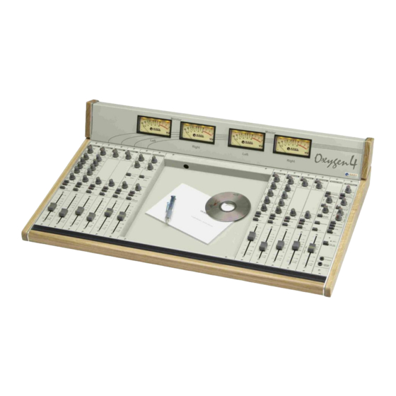
Oxygen 4
Broadcast Mixing Console
User Manual
Analog Broadcast
Mixing Console
(Rev. 3.0 ENG)
Main Office BOLOGNA: Via Caduti Di Sabbiuno 6/F
40011 Anzola Emilia - Bologna - Italy
Tel. +39 051 736555 - Fax. +39 051 736170
Regional Office BERGAMO: Via Italia 1 –
24030 Medolago (Bg) – Italy
Tel. +39 051 736555 - Fax. +39 051 736170
e-mail:
info@axeltechnology.com
- web site:
www.axeltechnology.com
Advertisement
Table of Contents

Subscribe to Our Youtube Channel
Related Manuals for Axel Oxygen 4


Summary of Contents for Axel Oxygen 4
- Page 1 Oxygen 4 Broadcast Mixing Console User Manual Analog Broadcast Mixing Console (Rev. 3.0 ENG) Main Office BOLOGNA: Via Caduti Di Sabbiuno 6/F 40011 Anzola Emilia - Bologna - Italy Tel. +39 051 736555 - Fax. +39 051 736170 Regional Office BERGAMO: Via Italia 1 –...
-
Page 2: Table Of Contents
OXYGEN 4 – AVAILABLE FRAME SIZE ......................4 OXYGEN 4 – AVAILABLE MODULES ......................... 5 OXYGEN 4 – AVAILABLE SCRIPT AND SLIDER (FADER) ................6 OXYGEN 4 – MODULI A RICHIESTA (GIA‟ PRESENTI NEL FRAME) ..............6 IMPORTANT NOTES ............................6 THIS MANUAL ..............................6 AVAILABLE FRAME SIZE PICTURES ........................ - Page 3 APPENDIX G – HOW TO CHANGE/SUBSTITUE A OXYGEN‟S 4 MODULE ............ 69 20.8 20.9 DIMENSIONS ..............................73 OXYGEN 4 TECHNICAL SPECIFICATIONS ....................... 74 WEEE Directive – Informativa RAEE ......................... 75 GARANZIA ................................76 DECLARATION OF ROHS CONFORMITY ......................76 CONTATTI AXEL TECHNOLOGY ........................77 AXEL | OXYGEN 4 SERIES - INTRODUCTION...
-
Page 4: Oxygen 4 Series - Introduction
Control Room and Speaker booth. Oxygen 4 console is available in four frame sizes: the Frame 10, which can contain 10 overall modules, the Frame 20 and the Frame 30. A MeterHood frame version (named VMH) is also available, which presents four traditional, needle backlit Vu Meters housed in an elegant meterbridge. -
Page 5: Oxygen 4 - Available Modules
A103040360 OX4-ST-2SSIO Momentary, opto duplicated Start/Stop control (A,B) from slider for stereo module A103040120 OX4-TELCO Telco module (interface for external telephone hybrids) A103040130 OX4-TELEF Telephone module with integrated hybrid A103040220 OX4-COV Cover Module AXEL | OXYGEN 4 SERIES - INTRODUCTION... -
Page 6: Oxygen 4 - Available Script And Slider (Fader)
1.5 IMPORTANT NOTES Start/Stop commands and VCA control options can not be fitted in the same Stereo module 1.6 THIS MANUAL This User Manual has been developed for Oxygen 4 and Oxygen 4 VMH series. AXEL | OXYGEN 4 SERIES - INTRODUCTION... -
Page 7: Available Frame Size Pictures
IN; Monitor, Master/Sub, 4Vu. Power Supply Unit , rackmount 1u 19'' 115/230Vac. A103040011 OX4-FR20 OXYGEN 4 Professional modular broadcast console frame 18 Frame size 20 Channel IN; Monitor, Master/Sub, 4Vu. Power Supply Unit , rackmount 1u 19'' 115/230Vac. AXEL | OXYGEN 4 SERIES - INTRODUCTION... - Page 8 Supply Unit , rackmount 1u 19'' 115/230Vac. A103040012 OX4-FR30 OXYGEN 4 Professional modular broadcast console frame 28 Frame size 30 Channel IN; Monitor, Master/Sub, 4Vu. Power Supply Unit , rackmount 1u 19'' 115/230Vac. AXEL | OXYGEN 4 SERIES - INTRODUCTION...
-
Page 9: Safety Warnings / Istruzioni Per La Sicurezza
It is recommended that all maintenance and service on the product should be carried out by the manufacturer or its authorised agents. The manufacturer cannot accept any liability whatsoever for any loss or damage caused by service, maintenance or repair by unauthorised personnel. AXEL | SAFETY WARNINGS / ISTRUZIONI PER LA SICUREZZA... -
Page 10: Safety Warnings
To completely separate from mains power (f.i. in the event of danger) unplug mains power cord. As the MAINS plug is the disconnect device, the disconnect device shall remain readily operable. AXEL | SAFETY WARNINGS... -
Page 11: Consignes De Sécurité Importantes
L’interrupteur d’alimentation interrompt un pôle du réseau d’alimentation excepté le conducteur de terre de protection. En cas de danger, debrancher le cordon d'alimentation. Parce que la prise du réseau de alimentation est utilisée comme dispositif de déconnexion, ce dispositif doit demeuré aisément accessible AXEL | CONSIGNES DE SÉCURITÉ IMPORTANTES... -
Page 12: Istruzioni Importanti Per La Sicurezza
è pertanto completo. Per ottenere un isolamento totale (ad esempio in caso di pericolo), scollegare il cordone di alimentazione. Inoltre, poichè la spina di alimentazione è utilizzata come dispositivo di sezionamento, essa deve restare facilmente raggiungibile AXEL | ISTRUZIONI IMPORTANTI PER LA SICUREZZA... -
Page 13: Wichtige Sicherheitshinweise
Hauptsicherung nur mit einer gleichwertigen austauschen (s. entsprechende Etikette). Vor Einschalten Netzspannungseinstellung am Gerät überprüfen bzw. anpassen. Inpoliger Netzschalter. In Notfälle oder für Wartungsarbeiten Netzkabel trennen. Der Netzstecker fungiert auch als Trennelement muss deshalb zugänglich bleiben AXEL | WICHTIGE SICHERHEITSHINWEISE... -
Page 14: Instrucciones Importantes De Seguridad
El interruptor de alimentación es unipolar. En el caso de peligro, desconecte el cable de alimentación. Porque la clavija de conexion a red sirve por la desconection de la unidad, la clavija debe ser ubicada en proximidad de la unidad AXEL | INSTRUCCIONES IMPORTANTES DE SEGURIDAD... -
Page 15: Unpacking And Inspection
The actual equipment Serial Number is indicated on the silver label stuck on the rear panel of the equipment closure. Tools And Equipment Needed Only standard technician’s tools are required to install this equipment. Axel Technology srl www.axeltechnology.com UNPACKING AND... -
Page 16: First Installation Recommendations
Technical Specifications table at the end of this user manual. CAUTION: TO REDUCE THE RISK OF ELECTRICAL SHOCK, ALWAYS DISCONNECT THE AC MAINS CABLE BEFORE ALTERING THE CHANGE-OVER SWITCH. NO USER SERVICEABLE PARTS INSIDE. REFER SERVICING TO QUALIFIED SERVICE PERSONNEL. Axel Technology srl www.axeltechnology.com FIRST INSTALLATION RECOMMENDATIONS... -
Page 17: Fuse Replacement
Uninsulated dangerous voltage are inside the enclosure, voltage that may be sufficient to constitute a risk of shock. Always disconnect to AC Mains before removing the top cover Axel Technology srl www.axeltechnology.com FIRST INSTALLATION RECOMMENDATIONS... -
Page 18: Protection Against Lightning
It is advisable to install several multiple mains connectors close to the Oxygen 4, with a master power switch to shut down all power to the studio.. -
Page 19: Position
If you are not sure Contact your Axel Technology agent for advice. 9.7 POSITION The console should be located in a convenient space commensurate with the use to which the console is being put. -
Page 20: Oxyygen 4 Block Diagram
LINE BALANCED REC-2 L PHONO UNBAL. GAIN PHONO UNBALANCED LINE BAL. GAIN FADER RING J1-J2 J3-J4 J5-J6 REC-2 R REMOTE RING MASTER L Analog Signal RING Logic Signal MASTER R Link RING Axel Technology srl www.axeltechnology.com OXYYGEN 4 BLOCK DIAGRAM... -
Page 21: Factory Preset Console Configuration
FACTORY PRESET CONSOLE CONFIGURATION 11 FACTORY PRESET CONSOLE CONFIGURATION Oxygen 4 comes from the factory with the following settings: MONO MODULES (A and B) ref to par. 0 The Mono module closest to the centre of the console (B) is set for Control Room microphones and Jumpers J2, J 4, J6 are closed (i.e. -
Page 22: Module Removing And Installation
Adjust the Gain trimmers on Mono rear modules if the signal is still too high with the main Gain turned down. It may be necessary to re-adjust the gain if changes are made to the equaliser or inserted signal processing. Axel Technology srl www.axeltechnology.com... -
Page 23: Mono Module
ALPS N-type 90° ultra smooth 100 mm sliders are provided on series. On request, to notify at order, ALPS K/VCA series sliders can be also fitted, the last ones controlling an internal high quality VCA circuitry. Axel Technology srl www.axeltechnology.com MONO MODULE... -
Page 24: Module Options And Jumper Settings
Relay #1 inside the Power Supply. This relay may be used to control an On Air Lamp (such as MR. LIGHT by Axel Technology). When the RELAY 2 jumper (J 5) is closed, the Fader opening is associated to the switch of Relay #2 inside the Power Supply. -
Page 25: Input Rear Panel
The A/B switch selects the INPUT B (Line) socket when depressed and the INPUT A (Mic) when released. A LED glows red when the INPUT B is selected. Both left and right signal paths are fed by the same mono input signal. Axel Technology srl www.axeltechnology.com MONO MODULE... -
Page 26: Gain Control
Rotation fully anticlockwise feeds the signal solely to the Left mix bus (Master & Sub outputs), while rotation clockwise sweeps the image to the Right mix bus (Master & Sub outputs). The centre applies 0 dB of gain to both L & R signals. Axel Technology srl www.axeltechnology.com MONO MODULE... -
Page 27: Master-Sub Routing Switches
The benefit is longer fader life, as the crackles and dropouts typical of the traditional audio faders are smoothed out. Axel Technology srl www.axeltechnology.com MONO MODULE... -
Page 28: Stereo Module
Start/Stop relay closures from slider OX4-ST-2SSIO momentary, optoinsulated Start/Stop control from slider (duplicated for Input A and B) NOTE: the here above listed Start/Stop options can not be added to slider VCA option. Axel Technology srl www.axeltechnology.com STEREO MODULE... -
Page 29: Start" Optional Remote Interface
The short-circuit will last as long as the slider is „open‟ (thus always providing a „latched‟ command). A + 15 VDC is supplied on Pin 1 via a 100 Ohm resistor. Please, consider than max current allowed on Start/Stop circuit is 100 mA. Axel Technology srl www.axeltechnology.com STEREO MODULE... -
Page 30: Ssir" Optional Remote Interface
Common – Start Relay NC – Start Relay NO – Start Relay Not Connected Not Connected Common – Stop Relay NC – Stop Relay NO – Stop Relay + 15 V frame Ground GND Axel Technology srl www.axeltechnology.com STEREO MODULE... -
Page 31: Interface Configuration
See previous section for command assignment to Input A or Input B. A + 15 VDC is supplied on Pin 1 via a 100 Ohm resistor. Please, consider that max current allowed on Start/Stop relays is 500 mA at 24 Vdc. Axel Technology srl www.axeltechnology.com STEREO MODULE... -
Page 32: Ssio Interface Pin Out
+ 15 V A Collector (START) A Collector (STOP) B Collector (START) B Collector (STOP) A Emitter (START) A Emitter (STOP B Emitter (START) B Emitter (STOP) frame Ground GND Connection Example (console internal view) Axel Technology srl www.axeltechnology.com STEREO MODULE... -
Page 33: Line / Phono Input B Setting
Phono configuration is suitable for record-players, as a RIAA equalization is featured. NOTE connection is possible only in unbalanced mode. Line configuration is suitable for 0 dB level signals (f.i., coming from tape player, tuners, Cd players, etc). Axel Technology srl www.axeltechnology.com STEREO MODULE... -
Page 34: Input Rear Panel
Start with a low setting, especially for professional equipment, checking the level on the meters using PFL, and increase it if you cannot reach an adequate signal level with the fader at maximum (refer also to par. 11.2). Axel Technology srl www.axeltechnology.com STEREO MODULE... -
Page 35: Equaliser
The Sub mix can be mixed into the main output mixbus (Master) (see MASTER routing switcher on the Sub module). This is a convenient way to use the SUB assigment switch as a subgroup system, creating new possibilities in the Oxygen 4 console. -
Page 36: Pfl Button
The benefit is longer fader life, as the crackles and dropouts typical of the traditional audio faders are smoothed out. Axel Technology srl www.axeltechnology.com STEREO MODULE... -
Page 37: Telco Module
ALPS N-type 90° ultra smooth 100 mm sliders are provided on series. On request, to notify at order, ALPS K/VCA series sliders can be also fitted, the last ones controlling an internal high quality VCA circuitry. Axel Technology srl www.axeltechnology.com TELCO MODULE... -
Page 38: Remote Interface Connection
It may be necessary to consult the hybrid manufacturer‟s user manual in order to control its functions. OXYGEN 4 Telco remote interface has been designed for direct connection to BOXTEL and MACROTEL 5 / 7 / 9 by Axel Technology. -
Page 39: Rear Panel Connections
14.5 SEND CONTROL It adjusts in the +/- 15 dB range the level of mix-minus signal which is sent to the telephone caller via the external telephone hybrid. Axel Technology srl www.axeltechnology.com TELCO MODULE... -
Page 40: Hook Switch And Ring Led
14.6 HOOK SWITCH AND RING LED The Hook switch remotely controls the Line hooking on suitable telephone hybrids (such as Macrotel 5,7,9 and BoxTel by Axel Technology). This switch connects / disconnects the hybrid from the telephone line and mutes the channel (ie. when Hook is depressed, Receive input is automatically muted). -
Page 41: Master-Sub Routing Switches
When the PFL button is deactivated: - the Master or Sub bus is automatically sent to the caller, regardless of the Master and Sub routing switches on the Telco module - the caller is broadcast with channel fader opened Axel Technology srl www.axeltechnology.com TELCO MODULE... -
Page 42: Fader
The benefit is longer fader life, as the crackles and dropouts typical of the traditional audio faders are smoothed out. Axel Technology srl www.axeltechnology.com TELCO MODULE... -
Page 43: Telephone Module
ALPS N-type 90° ultra smooth 100 mm sliders are provided on series. On request, to notify at order, ALPS K/VCA series sliders can be also fitted, the last ones controlling an internal high quality VCA circuitry. Axel Technology srl www.axeltechnology.com TELEPHONE MODULE... -
Page 44: Rear Panel
(typically Red & Green ) are used. 15.3 TELEPHONE LINE CONNECTIONS The Oxygen 4 – telephone hybrid module operates on analog telephone lines. MAKE SURE this appliance is connected to POTS / PSTN, analogue lines DO NOT CONNECT this appliance to digital Telephone lines DO NOT CONNECT this appliance to ADSL telephone lines, even if filtered. - Page 45 Alternatively you should disconnect all connectors from the device during a storm or when the device is going to be unsupervised or not used for a longer period of time. These measures will protect against damage by lightning or excess voltage. Axel Technology srl www.axeltechnology.com TELEPHONE MODULE...
-
Page 46: Receive Control
Rotation fully anticlockwise feeds the signal solely to the Left mix bus (Master & Sub outputs), while rotation clockwise sweeps the image to the Right mix bus (Master & Sub outputs). The centre applies 0 dB of gain to both L & R signals. Axel Technology srl www.axeltechnology.com TELEPHONE MODULE... -
Page 47: Master-Sub Routing Switches
The Sub mix can be mixed into the main output mixbus (Master) (see MASTER routing switcher on the Sub module). This is a convenient way to use the SUB assigment switch as a subgroup system, creating new possibilities in the Oxygen 4 console. -
Page 48: Fader
The benefit is longer fader life, as the crackles and dropouts typical of the traditional audio faders are smoothed out. Axel Technology srl www.axeltechnology.com TELEPHONE MODULE... -
Page 49: Master - Sub Module
(Master) programme output, allowing it to be used as audio subgroup primarily for production applications. The pre-fader Sub signal is also available for monitoring. Both the Master and Sub Main outputs can be independently switched in Mono mode. Axel Technology srl www.axeltechnology.com MASTER - SUB MODULE... -
Page 50: Rear Panel
Master (or Sub) outputs. The mono feed is usually used as the main output if you are broadcasting in mono, or have an AM service. Axel Technology srl www.axeltechnology.com MASTER - SUB MODULE... -
Page 51: Rec 1 Control Section
MASTER routing switcher allows the Sub mix (post-fader) to be mixed into the main output mixbus (Master). This is a convenient way to use the SUB assignment switch as a subgroup system, creating new possibilities in the Oxygen 4 console. The red LED inside the switch will illuminate accordingly. -
Page 52: Sub Fader
ALPS N-type 90° ultra smooth 100 mm sliders are provided on series. The scale shows the attenuation. Normal operating position is at the top „0‟ mark, providing overall 0 dB of gain. Axel Technology srl www.axeltechnology.com MASTER - SUB MODULE... -
Page 53: Monitor Module
17 MONITOR MODULE 17.1 INTRODUCTION The Oxygen 4‟s monitor section gives the operator an extensive set of resources. In addition to monitoring the Master and Sub audio buses, provision has been made for monitoring an external audio source. This stereo input (Tuner) is intended to be connected to microwave, FM or satellite receivers or another studio. -
Page 54: Module Options And Jumper Settings
When closed, the TB MIC jumper (J3) enables the console built-in microphone for TalkBack to Studio communications. When the jumper J4 is closed, the TalkBack to Studio button is associated to the cut-off of the C.ROOM SPEAKER output on the MONITOR module. Axel Technology srl www.axeltechnology.com MONITOR MODULE... -
Page 55: Rear Panel Connections
PCB (ref to previous paragraph). ** or amplified speakers that contain internal power amplifiers PWS (DC POWER) This is male SubD 9 pin socket which connects the Oxygen 4 mixer to the power supply. METER This is female SubD 9 pin socket which connects the Oxygen 4 mixer to the Meterbridge. -
Page 56: Studio Monitor Section
(ref to MONO Module settings - par. 0) *. For normal Studio speaker operation the mute LED must not be lit. * Speakers full muting may be required when a “live” microphone is located in the Studio. Axel Technology srl www.axeltechnology.com MONITOR MODULE... -
Page 57: Control Room Monitor Section
(ref to MONO Module settings - par. 0)**. For normal control room speaker operation the mute LED must not be lit. ** Speakers full muting may be required when a “live” microphone is located in the control room. Axel Technology srl www.axeltechnology.com MONITOR MODULE... -
Page 58: Tb To Studio Button And Tb Microphone
2) Press and hold the T.B. to Studio button: it will connect the Announcer„s voice audio source to the CRoom speakers. The voice audio signal will replace whatever signals are also present on this output. Axel Technology srl www.axeltechnology.com MONITOR MODULE... -
Page 59: Studio And Ctrl Room Phone Plugs
The 1/4” stereo jack sockets provide separate outputs for the Studio and Control Room phones outputs. Studio headphones can also be plugged into the back panel of this module (Speaker output, whenever set for headphones level – see par. 0). Axel Technology srl www.axeltechnology.com MONITOR MODULE... -
Page 60: Power Supply
18.2 REAR VIEW 18.3 DESCRIPTION The Oxygen 4 Power Supply (PWS) consists of a power transformer, selectable for 115 VAC or 230 VAC operation, rectifiers, filter capacitors and voltage regulators on a circuit board. The power supply is protected by a replaceable AC mains fuse located in the power entry socket plus internal fuses on the transformer‟s secondary outputs and self-protected current-limiting regulators. -
Page 61: Pws Relays
They are designed to illuminate external Studio and/or Control Room Warning/On Air lights (such as Mr Light by Axel Technology) showing that one or more microphones are „on air‟. Relays are intended for low voltage electric loads (e.g. 24 V), up to 10 A. -
Page 62: Main Ac Voltage Settings
18.6 MAIN AC VOLTAGE SETTINGS Before connecting the Oxygen 4 to mains power, determine the actual mains voltage and confirm that the Oxygen 4 has been configured correctly. As could be expected, an incorrect mains configuration could seriously damage the unit. - Page 63 AC Mains cord only switch on the power supply again and check whether all LEDs glow. Note: if the problem still persists, please contact Axel Technology technical department switch the power supply off connect the mixing console to the PWS...
-
Page 64: Meterbridge
19.1 VIEW 19.2 DESCRIPTION The Oxygen 4 mixer is fitted with VU / PPM meters. VU meters respond to an average signal level, whereas PPMs respond to peak changes (The PEAK LEDs are activated by the shortest transient peak, but remain „on‟ long enough to provide easy recognition). - Page 65 METERBRIDGE Axel Technology srl www.axeltechnology.com METERBRIDGE...
-
Page 66: Technical Appendix
20 TECHNICAL APPENDIX This section provides all the technical explanations, and the connection Pin Outs to and from the Oxygen 4 and Oxygen 4 VMH. Always refer to this technical appendix for connections and connection procedures. In case of differences between the documentation below and the hardware device please contact Axel Technology at the numbers and e-mail addresses shown at the end of this manual. -
Page 67: Appendix D - Balanced Audio Connection Xlr M - Jack
TECHNICAL APPENDIX 20.4 APPENDIX D – BALANCED AUDIO CONNECTION XLR M – JACK 20.5 APPENDIX E – UNBALANCED AUDIO CONNECTION PIN (RCA) AUDIO 20.6 APPENDIX F – BALANCED AUDIO CONNECTION JACK - JACK Axel Technology srl www.axeltechnology.com TECHNICAL APPENDIX... -
Page 68: Appendix F - Module Connection
MASTER (L&R), SUB (L&R), REC-1 (L&R), REC-2 (L&R) sockets Ground Ground Ring Out-of-phase (Cold) (-) In-phase (Hot) (+) 1/4” jack plug connectors for HEADPHONES and SPEAKERS sockets Ground Ground Ring Right Channel Left Channel Axel Technology srl www.axeltechnology.com TECHNICAL APPENDIX... -
Page 69: Appendix G - How To Change/Substitue A Oxygen"S 4 Module
TECHNICAL APPENDIX 20.8 APPENDIX G – HOW TO CHANGE/SUBSTITUE A OXYGEN’S 4 MODULE Turn the power OFF Unscrew the TOP screw using a „cross‟ screwdriver Unscrew the BOTTOM screw Axel Technology srl www.axeltechnology.com TECHNICAL APPENDIX... - Page 70 PULL the bottom part of the module UP 5) Slide the TOP part of the module off the rail and gently lift the module 6) Unlock the two hooks at the connector ends 7) disconnect the main cable bus Axel Technology srl www.axeltechnology.com TECHNICAL APPENDIX...
- Page 71 TECHNICAL APPENDIX 8) disconnect the top connector on the module‟ board Axel Technology srl www.axeltechnology.com TECHNICAL APPENDIX...
- Page 72 9) On the back of the console, remove the screws holding the module rear plate 10) take the rear module off 11) to mount the new module, follow the same instructions in reverse order Axel Technology srl www.axeltechnology.com TECHNICAL APPENDIX...
-
Page 73: Dimensions
TECHNICAL APPENDIX 20.9 DIMENSIONS OVERALL CONSOLE WIDTH 10 modules Frame 416 mm 20 modules Frame 802 mm 1188 mm 30 modules Frame ( with Script Tray ) VMH version: Axel Technology srl www.axeltechnology.com TECHNICAL APPENDIX... -
Page 74: Oxygen 4 Technical Specifications
OXYGEN 4 TECHNICAL SPECIFICATIONS 21 OXYGEN 4 TECHNICAL SPECIFICATIONS STEREO MODULE jack 1/4” INPUT A Stereo El. Bal. INPUT A nominal level 0 dBm (LINE) -15 to +15 dB gain control INPUT A impedance 10 kOhm jack 1/4” INPUT B... -
Page 75: Weee Directive - Informativa Raee
V súlade so smernicou 2002/96/ES o odpade z elekrických a elektronických zariadení (OEEZ) sa toto elektrické zariadenie nesmie odstranovat‘ ako netriedený komunálny odpad. Výrobok odstránte jeho vrátením v mieste nákupu alebo odovzdaním v miestnom zbernom zariadení na recyklovanie. WEEE Directive – Informativa Axel Technology srl www.axeltechnology.com RAEE... -
Page 76: Garanzia
Lead (Pb) Hexavalent Chromium (CrVl) Mercury (Hg) PBB (Flame Retardant) PBDE (Flame Retardant) Cadmium (Cd) Product Description: OXYGEN 4 – OXGEN 4 VMH Authorized Company Representative: Title of Signatory: Date: 28 December 2010 Christian Sighinolfi – Technical Manager Axel Technology srl www.axeltechnology.com... -
Page 77: Contatti Axel Technology
CONTATTI AXEL TECHNOLOGY 25 CONTATTI AXEL TECHNOLOGY Main Office BOLOGNA: Via Caduti Di Sabbiuno 6/F 40011 Anzola Emilia - Bologna - Italy Tel. +39 051 736555 - Fax. +39 051 736170 Regional Office BERGAMO: Via Italia 1 – 24030 Medolago (Bg) – Italy Tel.
Need help?
Do you have a question about the Oxygen 4 and is the answer not in the manual?
Questions and answers