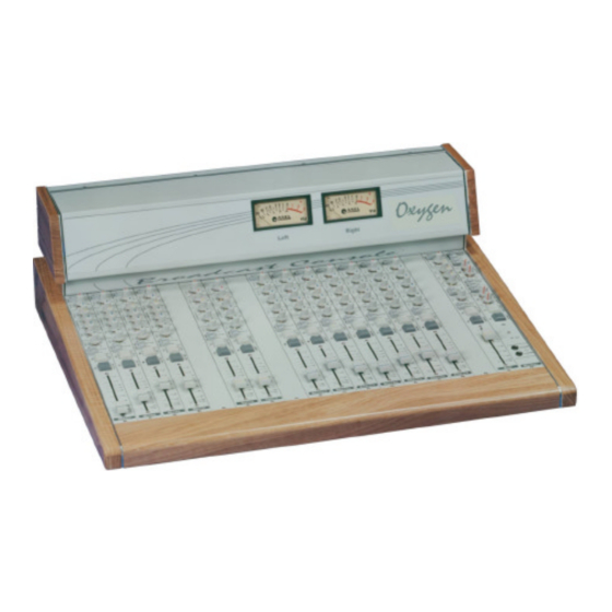
Axel Oxygen 5 Operating Manual
Broadcast console
Hide thumbs
Also See for Oxygen 5:
- User manual (64 pages) ,
- User manual (137 pages) ,
- User manual (124 pages)

Related Manuals for Axel Oxygen 5

Summary of Contents for Axel Oxygen 5
- Page 1 Operating Manual (Rev. 1.3) Oxygen 5 Broadcast Console AXEL TECHNOLOGY S.R.L. Web site: www.axeltechnology.com E-mail: info@axeltechnology.com...
-
Page 2: Table Of Contents
Oxygen 5 CONTENTS INSTALLATION – MIXING CONSOLE OVERVIEW ..................4 ..........................4 NPUT AND OUTPUT MODULES STEREO MODULE ..............................5 INTRODUCTION ..............................6 A ................................6 NPUT B ................................6 NPUT REMOTE INTERFACE .............................6 A-B I ............................8 NPUT ELECTOR GAIN C ..............................8 ONTROL ............................8 QUALIZATION ECTION BALANCE ............................8... - Page 3 Oxygen 5 COMPRESSOR S ..........................27 ECTION COMP ............................27 SWITCH 5.10 AUTO FADER ............................28 SWITCH 5.11 ..............................28 CONTROL 5.12 MASTER ..........................28 SWITCH 5.13 MASTER ..........................28 SWITCH 5.14 ..............................28 BUTTON 5.15 SLATE ..............................29 BUTTON 5.16 FADER ................................29 5.17 ..........................29 ODULE ONFIGURATION 5.18 MODULE CONFIGURATION........................30...
-
Page 4: Installation - Mixing Console Overview
1 SUB output, 2 Rec output (assignable to the Master or Sub bus), a compressor section with Auto Fader and Limiter functions, the connections to the DJ Console by AXEL TECHNOLOGY and the connection to an auxiliary signal... -
Page 5: Stereo Module
Oxygen 5 2 STEREO MODULE Input A REMOTE Interface Input B A-B Input Selector GAIN Control Equalization Section BALANCE Control MASTER and SUB switches PFL function START/STOP Button FADER Pag. 5... -
Page 6: Introduction
Oxygen 5 2.1 INTRODUCTION Stereo module is easily and readily configurable as line/line or line/phono depending on the user requirement. Input A is a line stereo input, while Input B (stereo) may be set through internal jumpers as line stereo or phono stereo (with built-in R.I.A.A. preamplifier). The module provides also a REMOTE interface to connect or control external equipment. - Page 7 Oxygen 5 Please note that: § the max current value provided by the Start/Stop photo transistors is 20 mA. § Interface phototransistors are not able to directly drive any external relais. Please use them to drive an external power transistor .
-
Page 8: A-B Input Selector
Oxygen 5 2.5 A-B INPUT SELECTOR It selects the input A (led switched off) without the pressed button; the input B (led switched on) with the pressed button. 2.6 GAIN CONTROL It sets the gain from -15dB to +15dB on the selected input (A or B). -
Page 9: Start Button
2.12 FADER The slider is one of the most important device in the mixer. For that reason, Axel Technology uses only slider by ALPS, one of the best manufactures in the field. The N type is provided on series. On demand, we can provide the K series and the K/VCA series too. - Page 10 Oxygen 5 • Phono/line input B setting: see J1, J2, J3, J4, J5, J6 on figure • If J12, J13, J14 and J15 (placed at the bottom of the board) are in the Start/Stop configuration (INDIRECT mode), you can get the...
-
Page 11: Mono Module
Oxygen 5 3 MONO MODULE Input A Input B Input A INSERT GAIN Input A Trimmer A-B Input Selector GAIN Control Equalisation Section Control PANORAMIC MASTER and SUB switches PFL button ON/OFF button FADER Pag. 11... -
Page 12: Introduction
Oxygen 5 3.1 INTRODUCTION The Mono module features two mono inputs (Input A and Input B). Input A is factory pre-set on microphone level but it can be also easily set on line level. Input B is set only on line level. -
Page 13: Gain Input A Trimmer
Oxygen 5 3.6 GAIN INPUT A TRIMMER You can use the multi-turns trimmer to fit the Micro level to the input level of the pre- amplification circuit. It’s highly recommended if the Gain potentiometer doesn’t amplify or attenuate enough the Micro signal. Adjust the trimmer to reach the 0 dB PFL output level corresponding to the Gain control central position (read the level on the VU-Meter). -
Page 14: Master And Sub Switches
On/Off function either in local mode (through related button) or in remote mode, through an external device (‘DJ Console’ by Axel Technology) linked to the SUB module. Thanks to it, the speaker (normally located in studio) is able to remotely switch the mixer module related to his microphone. -
Page 15: Summary Of The Services/Functions Featured By The Module
‘Larsen’ effects- see jumper J3 and J4) • Switching of two relays built-in in the power supply (relay 1 and 2- see jumper J6 and J7). You could use this function to light an ‘On Air’ lamp (as Mr. Light by AXEL TECHNOLOGY) 3.15 FADER The slider is one of the most important device in the mixer. -
Page 16: Module Configuration
Oxygen 5 3.16 MODULE CONFIGURATION On the MONO module board you find 10 Jumpers allowing different operation modes and functions. To change a jumper setting, please: • switch off the console (every intervention on the modules always requires the mixer switching off !) •... - Page 17 Oxygen 5 If J1 is present, Phantom voltage is enabled on input A • If J2 is present, input A is set for MICRO level (otherwise is set on Line level) • If J3 is on ‘Fader Enable’ position, every time you open the slider (no matter of the On/Off key) the Studio monitor loudspeakers are cut off.
-
Page 18: Telco Module
Oxygen 5 4 TELCO MODULE SEND Output REMOTE interface RECEIVE Input REC OUT Output SEND GAIN Control RECEIVE GAIN Control Equalisation Section PAN Control MASTER and SUB switches PRIVATE Button HOOK Button FADER Pag. 18... -
Page 19: Send Output
4.1 SEND OUTPUT The Send output allows to send to the telephone line - through an external phone hybrid (e.g. MACROTEL7 by AXEL Technology) - the signal composed by the sum of the output signals from every module except the Telco one. -
Page 20: Rec Out Output
Oxygen 5 THE CONNECTOR SUPPLIES THE FOLLOWING VOLTAGES: • + 6 V (pin 6) • GND (pin 1) These voltages can be used to polarize external optoisolator devices. We suggest to use a Ω (or more) resistor in series connection with the phototransistor emitter to prevent the risk of damages to the photocoupler, due to extra-high current. -
Page 21: Panoramic Control
Oxygen 5 4.8 PANORAMIC CONTROL The PAN control allows sound balancing between Left and Right output channels. In the central position the gain is 0 dB for both channels. 4.9 MASTER AND SUB SWITCHES MASTER and SUB switches connect the module to the Master and/or Sub outputs. -
Page 22: Hook Button
‘hook’ the telephone line by pressing the Hook button: the led lights firmly 4.12 FADER The slider is one of the most important device in the mixer. For that reason, Axel Technology uses only slider by ALPS, one of the best manufactures in the field. - Page 23 Oxygen 5 J1 enables the recording of Send signal through the Rec Out socket. J2 enables the recording of Receive signal through the Rec Out socket. If J1,J2 are both present, Rec Out output provides the sum of Send/Receive signals.
-
Page 24: Sub Module
Oxygen 5 SUB MODULE EXT IN Input REMOTE Interface SUB Output INSERT REC 1-2 Outputs EXTERNAL FADER switch EXT GAIN Control COMPRESSOR Section SUB to COMP switch AUTO FADER switch BALANCE Control EXT to MASTER switch SUB to MASTER switch... -
Page 25: Sub Output
Ring Signal Input 5.3 REMOTE INTERFACE REMOTE interface is based on a SUB DB 9P female connector. The SUB interface is especially designed for the connection to, AXEL Technology DJ Console equipment, that allows: • The On/Off remote control – through a button placed on the DJ Console panel - of the Mono modules (if properly set). -
Page 26: External In Input
Oxygen 5 Pin-out SUB D 9P female: Pin 1 GND Pin 2 Enables the Talk Back function if you supplies + 6 V ÷ Pin 3 DC DUCK: by feeding a 0 6 V tension you can control the Sub VCA Pin 4 N.C. -
Page 27: Ext Gain Control
Oxygen 5 • The remote enabling of the Talk Back from Studio to Control Room. • The level fading of the comprehensive output signal coming out from the Sub module (which can be assigned to the Master module by pressing the ‘Sub to Master’ button on the Sub module). -
Page 28: Auto Fader Switch
Oxygen 5 5.10 AUTO FADER SWITCH AUTO FADER switch enables the automatic level adjustment of a signal (available on the input of the Sub module) depending on the level modulation of another signal (available on the input of the Master module). -
Page 29: Slate Button
Rec Out sockets). 5.16 FADER The slider is one of the most important device in the mixer. For that reason, Axel Technology uses only slider by ALPS, one of the best manufactures in the field. The N type is provided on series. On demand, we can provide the K series and the K/VCA series too. -
Page 30: Module Configuration
Oxygen 5 5.18 MODULE CONFIGURATION If J5 is present, the PFL signal turns to an AFL (After Fader Listen) signal Pag. 30... -
Page 31: Master Module
Oxygen 5 6 MASTER MODULE TUNER Input Power Supply Connector MASTER Output VU Meter Connector STUDIO Output CONTROL ROOM Output STUDIO Section CONTROL ROOM Section PFL RST Button TALK BACK function Microphone STUDIO Headphone CTRL ROOM Headphone Pag. 31... -
Page 32: Master Output
Oxygen 5 6.1 MASTER OUTPUT The two output sockets are electronically balanced on female stereo Jack with 0 dB gain. The pin-out presents standard configuration: • Sleeve Ground • Tip Signal • Ring Return We suggest to use balanced links. -
Page 33: Control Room Section
Oxygen 5 6.4 CONTROL ROOM SECTION The CTRL ROOM section allows the listening (on the studio loudspeakers and headphones) of the source selected by the four buttons TUNER, EXT, MASTER and PFL. If you press simultaneously two or more selections (e.g. Tuner and Master), you can listen to the sum of the selected sources. -
Page 34: Meter Connector
A Talk Back function from Studio to Control Room is also available through the DJ Console’ by Axel Technology.. Thanks to this equipment (connected to the SUB module) the speaker (normally located in the studio) is able to remotely switch the mixer module related to his microphone. - Page 35 Oxygen 5 Please refer to the following figure and to the ‘Factory preset jumper configuration’ chapter at the end of this manual before altering jumper configurations. If J1 is present, the Master internal microphone is enabled for ‘Talk Back to Studio’ function...
-
Page 36: Power Supply
Oxygen 5 7 POWER SUPPLY FRONTAL VIEW REAR VIEW 7.1 AC VOLTAGE (110-220 V Attention! Before starting the power supply, please check that the line supply voltage corresponds to that indicated in the rear of power supply. Power supply is ex-work set for 220 V (if not otherwise required). -
Page 37: Connection Between Console And Power Supply
• switch on the power supply again and verify that every led on the front panel switches on (except relais 1 and 2). Note: if the problem is still present, please contact Axel Technology technical office •... -
Page 38: Vu Meter
Oxygen 5 8 VU METER 8.1 MIXER CONNECTION The MET connector placed on Master module transfers the supply voltages and the signals feeding the VU-METER and the (optional) TIMERs. The connector type is SubD- 9 female. Please make sure the Met connector is on site. -
Page 39: Timer (Optional)
Oxygen 5 9 TIMER (optional) By request, up to two Timer modules are available to be installed on the mixer cover. The Timer feature the time count up showing minutes, seconds and tenth of seconds if time duration does not exceed 1 hour and hours, minutes and seconds if time duration exceeds 1 hour. -
Page 40: Factory Preset Module Configurations
Oxygen 5 11 FACTORY PRESET MODULE CONFIGURATIONS • The following images show the factory pre-set, standard jumper setting. Please refer to these images and to the relates chapters before altering jumper position. Please note: every intervention on the modules always requires the mixer switching off ! 11.1 STEREO MODULE –... -
Page 41: Mono Module - Factory Preset Jumper Configuration
Oxygen 5 11.2 MONO MODULE – FACTORY PRESET JUMPER CONFIGURATION J1 not present J2 present (Micro input Level) _________________________________________ Module setting for STUDIO microphones. By default, every mono module (excluding the last one on the right) is factory preset for the Studio microphones (“Talk Back to Control Room”... -
Page 42: Telco Module - Factory Preset Jumper Configuration
Oxygen 5 11.3 TELCO MODULE – FACTORY PRESET JUMPER CONFIGURATION J1 is present J2 is present J8 is present Pag. 42... -
Page 43: Master Module - Factory Preset Jumper Configuration
Oxygen 5 11.4 MASTER MODULE – FACTORY PRESET JUMPER CONFIGURATION J1 Not Present Pag. 43... -
Page 44: Sub Module - Factory Preset Jumper Configuration
Oxygen 5 11.5 SUB MODULE – FACTORY PRESET JUMPER CONFIGURATION Rec1 and Rec2 set as Master output Pag. 44... -
Page 45: Warranty
This warranty does not cover damage resulting from accident, misuse or abuse, lack of reasonable care, the affixing of any attachment not provided with the product, loss of parts or inadequate repairs. AXEL engineers are constantly working to improve the quality of our products. Specifications are, therefore, subject to change without notice. - Page 46 Oxygen 5 FIG. 3 Balanced microphone connection FIG. 4 Unbalanced connections for STUDIO / CTRL ROOM monitor loudspeakers FIG. 5 Unbalanced connection for STEREO module, EXT IN socket, TUNER IN socket Pag. 46...
Need help?
Do you have a question about the Oxygen 5 and is the answer not in the manual?
Questions and answers