Table of Contents
Advertisement
Desktop:
MDS932AE-10BT-R2
MDS932AE-FXO-R2
MDS932AE-FXS-R2
MDS933AE-10BT-R2
Rack Cards:
MDS932C-1-R2
MDS932C-2-R2 / MDS933C-R2
G.SHDSL Modem following the Restriction of Hazardous Substances Directive (RoHS)
USER MANUAL
Version
Revision
Document name
User Manual
1.9
22. May 2006
MDS932-933AE-10BT-R2_FXO-FXS-R2.doc
Advertisement
Table of Contents

Subscribe to Our Youtube Channel
Related Manuals for Black Box MDS932AE-10BT-R2


Summary of Contents for Black Box MDS932AE-10BT-R2
- Page 1 User Manual Desktop: MDS932AE-10BT-R2 MDS932AE-FXO-R2 MDS932AE-FXS-R2 MDS933AE-10BT-R2 Rack Cards: MDS932C-1-R2 MDS932C-2-R2 / MDS933C-R2 G.SHDSL Modem following the Restriction of Hazardous Substances Directive (RoHS) USER MANUAL Version Revision 22. May 2006 Document name MDS932-933AE-10BT-R2_FXO-FXS-R2.doc...
- Page 2 User Manual © Copyright ©2006 by Black Box Network Services. The contents of this publication may not be reproduced in any part or as a whole, transcribed, stored in a retrieval system, translated into any language, or transmitted in any form or by any means, electronic, mechanical, magnetic, optical, chemical, photocopying, manual, or otherwise, without the prior written permission of Black Box Network Services.
-
Page 3: Table Of Contents
User Manual VERSION CONTROL.......................5 GENERAL INFORMATION.....................7 DESCRIPTION OF THE DEVICE ...................8 Exterior design Desktop models ................8 Exterior design Rack Card models (MDS932C-1/2 or MDS933C-R2) ....10 RULES OF SWITCHING....................12 The DESKTOP delivery set..................12 The RACK CARD delivery set................12 Connection rules ....................12 Communication parameters of the terminal configuration........13 THE COMMAND SYSTEM ...................14 Basic rules......................14... - Page 4 User Manual TECHNICAL SPECIFICATIONS...................24 STORAGE CONDITIONS .....................25 CONNECTOR’S DESCRIPTION ..................26 DSL Connector Desktop units (MDS932/933AE-10BT-R2) .........26 DSL Connector for RACK CARD units (MDS932C-1/2-R2 (MDS933C-R2)) ..26 Monitor Connector....................27 PC and Hub Connectors ..................27 Line1 and Line2 Connector (MDS932AE-FXO/FXS-R2) ........28 DESCRIPTION OF INTERFACE CABLES..............29 10.1 Ethernet cable ......................29 10.2 DSL cable......................29 Version: 1.9...
-
Page 5: Version Control
User Manual VERSION CONTROL Version Date Major changes to previous version 31.12.2001 Initial version of the manual corresponding to version 1.2 of the device micro program 23.10.2003 New function description corresponding to software release V1.6 Corrected Connecter description 9.1 Changed DSL cable to twisted type 10.2 26.01.2004 Manual corresponding to software version 1.7 Implementation of RACK CARD models... - Page 6 User Manual EU Directive 2002/96/EC and EN50419 This equipment is marked with the above recycling symbol. It means that at the end of the life of the equipment you must dispose of it separately at an appropriate collection point and not place it in the normal domestic unsorted waste stream.
-
Page 7: General Information
User Manual 1 GENERAL INFORMATION • High-speed symmetrical data transmission over physical copper twisted pair with the 135 Ohm impedance according to ETSI TS 101 135. • ITU-T G.991.2 (G.shdsl) line encoding. • Line rate in the range from 72 Kbit/s to 2320 Kbit/s. Line rate in the range from 144 Kbit/s to 4624 Kbit/s (4W models only) •... -
Page 8: Description Of The Device
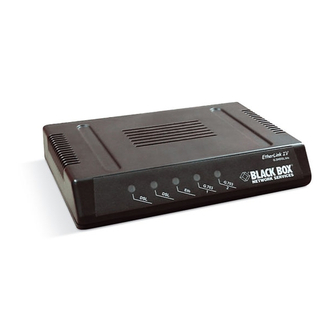
User Manual 2 DESCRIPTION OF THE DEVICE 2.1 Exterior design Desktop models The front panel of the device has 3 LEDs or 5 LEDs with FXO/FXS: Status informs the user about the status of the local device. The following four statuses are possible «blinking red»... - Page 9 User Manual The back panel of the MDS932AE-10BT-R2 and MDS933AE-10BT-R2 modem has: • The grounding bolt of the modem (option); • The “12Vdc / POWER“ connector. The connection of the modem to the 230 V power supply is implemented using an external power supply unit;...
-
Page 10: Exterior Design Rack Card Models (Mds932C-1/2 Or Mds933C-R2)
User Manual 2.2 Exterior design Rack Card models (MDS932C-1/2 or MDS933C-R2) Version: 1.9 Page. 10 of 29... - Page 11 User Manual Status(L) informs the user about the status of the local device. The following four statuses are possible «blinking red» informs the user about malfunctioning of the modem’s hardware and software. In this case, the modem is out of order and should be submitted to the service center for being repaired.
-
Page 12: Rules Of Switching
User Manual 3 RULES OF SWITCHING 3.1 The DESKTOP delivery set The delivery set includes: • the subscriber access device (a modem) • the power supply source (an AC adapter) • the cables for the line connections 3.2 The RACK CARD delivery set The delivery set includes •... -
Page 13: Communication Parameters Of The Terminal Configuration
User Manual 3.4 Communication parameters of the terminal configuration It is necessary to set the following parameters to monitor the modem: • transmission rate – 9600; • data bits – 8; • parity – none; • number of stop bits – 1; •... -
Page 14: The Command System
User Manual 4 THE COMMAND SYSTEM 4.1 Basic rules After the command is typed, press <enter>. The <Backspace> key is used to edit commands. It is necessary to input item number, for choosing menu item, You can use “PageUP”, “PageDown” and “Space” keys, for scrolling list of available value of parameters, The “Esc”... -
Page 15: Performance Management Submenu
User Manual 4.3 Performance management submenu Upon activation of the performance management submenu the following message will be displayed. Performance Management 1.Loop Status... 4.EtherNet Status... 7.HDLC Status... Select item number or ESC to Upper level menu>> 4.3.1 Loop Status submenu Upon activation of the performance management submenu the following message will be displayed. -
Page 16: Ethernet Status Submenu
User Manual 4.3.2 Ethernet Status submenu Upon activation of the performance management submenu the following message will be displayed. Performance Management->EtherNet Status Link:Link down Link Speed:---- Link Duplex:---- Used Entries:0 Tx Packets:0 Rx Packets:0 Fwd Packets:0 Drop Packets:0 Speed:Auto Duplex:Auto MAC Address: 00-00-00-00-00-00 1.Clear Counters Select item number or ESC to Upper level menu>>... -
Page 17: Hdlc Status Submenu
User Manual 4.3.3 HDLC Status submenu This menu contains statistical information about the HDLC packets that are sent between master and slave. Perfomance Managment->HDLC Status Channel_A Channel_B HDLC Tx Cnt:0 HDLC Tx Cnt:0 HDLC Rx Cnt:0 HDLC Rx Cnt:0 HDLC Fwd Cnt:0 HDLC Fwd Cnt:0 HDLC Drop Cnt:0 HDLC Drop Cnt:0... -
Page 18: Dsl Setup
User Manual 4.4.1 DSL Setup In this menu you can setup the DSL link. When you have selected that menu, the following will appear: Configuration Management->DSL Setup 1.[Loop 1 Operation Mode]:Slave 2.[Loop 1 Auto/Fixed]:Fixed 4.[Loop 1 Min. Connection Speed]:72K(1N) 5.[Loop 1 Max. Connection Speed]:2312K(36N) 6.[Loop 1 Annex]:B 7.[Loop 1 Tx Level Adjustment]:0 dB 19.[2W/4W]:2W... - Page 19 User Manual 4.4.1.4 Fixed Connection Speed (only if Fixed is selected) • In the Fixed Connection Speed menu, you can specify your desired speed in the range of 72 kbps to 2312 kbps for 2wire units and 528 kbps to 4624 kbps for 4wire models 4.4.1.5 Annex •...
-
Page 20: Ethernet Setup Submenu
User Manual 4.4.2 Ethernet Setup submenu Configuration Management->EtherNet Setup 1.[Speed]:Auto 2.[Duplex Mode]:Auto 3.[Disable Mac Filter]:No 4.IP Address>>192.168.5.105 5.Subnet Mask>>255.255.255.0 6.Gateway Address>>192.168.5.1 8.NMS IP Address>>192.168.5.32 9.Read Community>> 10.Write Community>> 11.Trap Community>> 12.[Enable TFTP Server]:No 13.[DSL Reboot]:No 14.[Time before Reboot]:30min Select item number or ESC to Upper level menu>> •... -
Page 21: Profile Submenu
User Manual 4.4.3 Profile submenu Users can save and load up to 4 profiles for different tasks. The Profile 0 is the default profile during power on. Users have to save all new value of parameters before power off. 4.4.4 Erase NVRAM Users can erase the non volatile ram. -
Page 22: Tftp Upload
User Manual 5 TFTP UPLOAD 5.1 Unit preparation Its suggested to connect the PC Terminal to the monitor connector for the observation of the download procedure. • Enter the Ethernet Setup submenu. • Enter menu point [Enable TFTP Server] and switch TFTP on •... -
Page 23: Snmp
User Manual 6 SNMP 6.1 Traps The unit supports the following traps: Trap Description Cold start Sent on unit startup Linkup Sent on DSL link up Linkdown Sent on DSL link loss Authorization Error Sent on reception of a wrong community string (hacker attack) Version: 1.9 Page. -
Page 24: Technical Specifications
User Manual 7 TECHNICAL SPECIFICATIONS The main technical specifications of modems of the Black Box family are presented below in the table. Line interface. Standard ETSI 101 135 Regulation RoHS 2002/95/EG Number of pairs 1 or 2 Line rate 2 wire models 72 –... -
Page 25: Storage Conditions
С. The equipment can also withstand air-transport at a low air pressure of 12 о kPa (90 Torr) at -50 С. The packed equipment of the Black Box family can be stored within 12 months (from the date transshipment including transporting... -
Page 26: Connector's Description
User Manual 9 CONNECTOR’S DESCRIPTION 9.1 DSL Connector Desktop units (MDS932/933AE-10BT-R2) Type: RJ-45, 8 pin Number Signal Assignment RJ-45 LB,a Ttp (4W model only) LA,a LA,b ring LB,b ring (4W model only) 9.2 DSL Connector for RACK CARD units (MDS932C-1/2-R2 (MDS933C-R2)) Type: RJ-45, 8 pin Number Signal... -
Page 27: Monitor Connector
User Manual 9.3 Monitor Connector Type: Sub-D9, female Number Signal Assignment Transmit data Receive data Data terminal ready SGND Signal ground female 9.4 PC and Hub Connectors Type: RJ-45 Number PC assignment HUB assignment RJ-45 Version: 1.9 Page. 27 of 29... -
Page 28: Line1 And Line2 Connector (Mds932Ae-Fxo/Fxs-R2)
User Manual 9.5 Line1 and Line2 Connector (MDS932AE-FXO/FXS-R2) Type: RJ-11, 4 pin Number Signal Assignment RJ-11 LA,a LA,b ring Version: 1.9 Page. 28 of 29... -
Page 29: Description Of Interface Cables
User Manual 10 DESCRIPTION OF INTERFACE CABLES 10.1 Ethernet cable Side А Color of wire Side B white/green green/white white/orange blue/white white/blue orange/white white/brown. brown/white 10.2 DSL cable Side А Color of wire Side B white/green green/white white/orange blue/white white/blue orange/white white/brown.
Need help?
Do you have a question about the MDS932AE-10BT-R2 and is the answer not in the manual?
Questions and answers