Table of Contents
Advertisement
Quick Links
Advertisement
Table of Contents

Related Manuals for Black Box MDS932C-1


Summary of Contents for Black Box MDS932C-1
- Page 1 User Manual MDS932AE-10BT STANDALONE MDS932AE-FXO STANDALONE MDS932AE-FXS STANDALONE MDS933AE-10BT STANDALONE MDS932C-1 RACK-CARD MDS932C-2 RACK-CARD G.SHDSL Modem USER MANUAL Version Revision 09. February 2005 Document name MDS933AE-v1.3.pdf...
- Page 2 User Manual © Copyright ©2005 by BLACK BOX Network Services AG. The contents of this publication may not be reproduced in any part or as a whole, transcribed, stored in a retrieval system, translated into any language, or transmitted in any form or by any means, electronic, mechanical, magnetic, optical, chemical, photocopying, manual, or otherwise, without the prior written permission of BLACK BOX Network Services AG.
-
Page 3: Table Of Contents
User Manual VERSION CONTROL......................5 GENERAL INFORMATION..................6 ORDER INFORMATION ..................... 7 DESCRIPTION OF THE DEVICE ................8 Exterior design Desktop models ............... 8 Exterior design Rack Cards models..............10 RULES OF SWITCHING..................12 The Desktop delivery set................. 12 The Rack Card delivery set................12 Connection rules ..................... - Page 4 User Manual DESCRIPTION OF INTERFACE CABLES.............. 25 Ethernet cable ....................25 DSL cable......................25 Version: 1.2 Page. 4 of 25...
-
Page 5: Version Control
User Manual VERSION CONTROL Version Date Major changes to previous version 31.12.2001 Initial version of the manual corresponding to version 1.2 of the device micro program 23.10.2003 New function description corresponding to software release V1.6 Corrected Connecter description 9.1 Changed DSL cable to twisted type 10.2 26.01.2004 Manual corresponding to software version 1.7 Implementation of rack card models... -
Page 6: General Information
User Manual 1 GENERAL INFORMATION • High-speed symmetrical data transmission over one physical copper twisted pair with the 135 Ohm impedance according to ETSI TS 101 135. • ITU-T G.991.2 (G.shdsl) line encoding. • Line rate in the range from 72 Kbit/s to 2320 Kbit/s in 2 wire mode Line rate in the range from 400 Kbit/s to 4624 Kbit/s in 4 wire mode •... -
Page 7: Order Information
User Manual ORDER INFORMATION MDS932AE-10BT Standalone Modem Discovery, G.shdsl, 10/100Base-T Bridge, VLAN, Adapter 220 Vac Rackcard Modem Discovery, G.shdsl, 10/100Base-T Bridge, MDS932C-1 VLAN MDS932C-2 Rackcard Dual Modem Discovery, G.shdsl, 10/100Base-T Bridge, VLAN MDS933AE-10BT Standalone Modem Discovery, G.shdsl, 1 or 2 pairs, up to 4.6Mbps, 10/100Base-T Bridge, VLAN, Adapter 220 Vac... -
Page 8: Description Of The Device
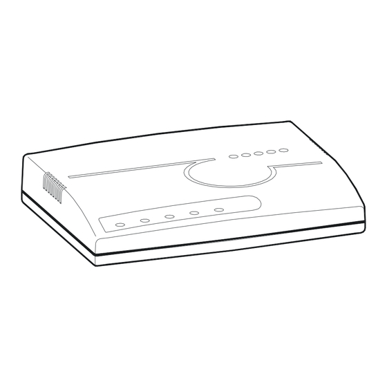
User Manual 2 DESCRIPTION OF THE DEVICE 2.1 Exterior design Desktop models The front panel of the device has 3 LEDs: LOCAL informs the user about the status of the local device. The following four statuses are possible «blinking red» informs the user about malfunctioning of the modem’s hardware and software. - Page 9 User Manual • The grounding bolt of the modem (option); • The “AC12V” power connector. The connection of the modem to the 220 V power supply is implemented using an external power supply unit; • the “Monitor” connector to control the modem and store statistics; •...
-
Page 10: Exterior Design Rack Cards Models
User Manual 2.2 Exterior design rack card models Version: 1.2 Page. 10 of 25... - Page 11 User Manual Status(L) informs the user about the status of the local device. The following four statuses are possible «blinking red» informs the user about malfunctioning of the modem’s hardware and software. In this case, the modem is out of order and should be submitted to the service center for being repaired.
-
Page 12: Rules Of Switching
User Manual 3 RULES OF SWITCHING 3.1 The standalone delivery set The delivery set includes: • the subscriber access device (a modem) • the power supply source (an AC adapter) • the cables for the line connections 3.2 The rack-card delivery set The delivery set includes: •... - Page 13 User Manual To update the information on the screen use the “Enter” key. The following menu will appear on the screen. Input Password: Please enter your programmed password. The unit will be delivered with the default password “admin” After entering the password the following menu will appear. Discovery G.SHDSL Ethernet Monitor V1.7 +-----------------------+...
-
Page 14: The Command System
User Manual 4 THE COMMAND SYSTEM 4.1 Basic rules After the command is typed, press <enter>. The <Backspace> key is used to edit commands. It is necessary to input item number, for choising menu item, You can use “PageUP”, “PageDown” and “Space” keys, for scrolling list of available value of parameters, The “Esc”... -
Page 15: Performance Management Submenu
User Manual 4.3 Performance management submenu Upon activation of the performance management submenu the following message will be displayed. Performance Management 1.Loop Status... 4.EtherNet Status... Select item number or ESC to Upper level menu>> 4.3.1 Loop Status submenu Upon activation of the performance management submenu the following message will be displayed. -
Page 16: Ethernet Status Submenu
User Manual 4.3.2 Ethernet Status submenu Upon activation of the performance management submenu the following message will be displayed. Performance Management->EtherNet Status Link:Link down Link Speed:---- Link Duplex:---- Used Entries:0 Tx Packets:0 Rx Packets:0 Fwd Packets:0 Drop Packets:0 Speed:Auto Duplex:Auto MAC Address:00-00-00-00-00-00 1.Clear Counters Select item number or ESC to Upper level menu>>... -
Page 17: Dsl Setup
User Manual 4.4.1 DSL Setup In this menu you can setup the DSL link. When you have selected that menu, the following will appear: Configuration Management->DSL Setup 1.[Loop 1 Operation Mode]:Slave 2.[Loop 1 Auto/Fixed]:Fixed 5.[Loop 1 Fixed Connection Speed]:2312K(36N) 6.[Loop 1 Annex]:A/B 7.[Loop 1 Tx Level Adjustment]:0 dB 18.[2W/4W]:2W Select item number or ESC to Upper level menu>>... - Page 18 User Manual 72 kbps to 2312 kbps for 2wire units and 400 kbps to 4624 kbps for 4wire models 4.4.1.5 Annex • With the Appendix menu you can choose between A, B, A / B. If you don’t know what Annex you have to setup, and then use the A / B configuration.
-
Page 19: Ethernet Setup Submenu
User Manual 4.4.2 Ethernet Setup submenu Configuration Management->EtherNet Setup 1.[Speed]:Auto 2.[Duplex Mode]:Auto 3.[Disable Mac Filter]:No 4.IP Address>>192.168.5.105 5.Subnet Mask>>255.255.255.0 6.Gateway Address>>192.168.5.1 Select item number or ESC to Upper level menu>> • In the Speed menu, you can setup the Ethernet speed to the following states: 10M, 100M or Auto •... -
Page 20: Technical Specifications
User Manual 5 TECHNICAL SPECIFICATIONS The main technical specifications of modems of the Black Box family are presented below in the table. Line interface. Standard ETSI 101 135 Number of pairs Line rate 2 wire models 72 – 2312 Kbit/s 4 wire models 400 –... -
Page 21: Storage Conditions
С. The equipment can also withstand air-transport at a low air pressure of о 12 kPa (90 Torr) at -50 С. The packed equipment of the Black Box family can be stored within 12 months (from the date of transshipment including transporting time) in storage rooms without heating о о... -
Page 22: Terms To Transport
• relative air humidity up to 100% at 25 С (within 10 days). The equipment of the Black Box family should be packed and withstand transportation by: • motor transport with the number of transshipments no more than four: •... -
Page 23: Connector's Description
User Manual 8 CONNECTOR’S DESCRIPTION 8.1 DSL Connector Type: RJ-45, 8 pin Number Signal Assignment RJ-45 LB,a Tip (4W model only) LA,a LA,b ring LB,b ring (4W model only) 8.2 Monitor Connector Type: Sub-D9, female Number Signal Assignment Transmit data Receive data Data terminal ready SGND... -
Page 24: Pc And Hub Connectors
User Manual 8.3 PC and Hub Connectors Type: RJ-45 Number PC assignment HUB assignment RJ-45 8.4 Line1 and Line2 Connector (FXO/FXS) Type: RJ-11, 4 pin Number Signal Assignment RJ-11 LA,a LA,b ring Version: 1.2 Page. 24 of 25... -
Page 25: Page. 3 Of
User Manual 9 DESCRIPTION OF INTERFACE CABLES 9.1 Ethernet cable Side А Color of wire Side B white/green green/white white/orange blue/white white/blue orange/white white/brown. brown/white 9.2 DSL cable Side А Color of wire Side B white/green green/white white/orange blue/white white/blue orange/white white/brown.
Need help?
Do you have a question about the MDS932C-1 and is the answer not in the manual?
Questions and answers