
Subscribe to Our Youtube Channel
Related Manuals for Black Box MDR100A-R4


Summary of Contents for Black Box MDR100A-R4
- Page 1 © Copyright 2000. Black Box Corporation. All rights reserved. 1000 Park Drive • Lawrence, PA 15055-1018 • 724-746-5500 • Fax 724-746-0746...
- Page 2 Order toll-free in the U.S. 24 hours, 7 A.M. Monday to midnight Friday: 877-877-BBOX SUPPORT FREE technical support, 24 hours a day, 7 days a week: Call 724-746-5500 or fax 724-746-0746 INFORMATION Mail order: Black Box Corporation, 1000 Park Drive, Lawrence, PA 15055-1018 Web site: www.blackbox.com • E-mail: info@blackbox.com...
- Page 4 TRADEMARKS TRADEMARKS USED IN THIS MANUAL Microsoft and Windows are registered trademarks of Microsoft Corporation. pcANYWHERE is a registered trademark of Dynamic Microprocessor Associates, Inc. UL is a registered trademark of Underwriters Laboratories, Incorporated. Any other trademarks used in this manual are acknowledged to be the property of the trademark owners.
- Page 5 INDUSTRIAL MODEM RF115 FEDERAL COMMUNICATIONS COMMISSION CANADIAN DEPARTMENT OF COMMUNICATIONS RADIO FREQUENCY INTERFERENCE STATEMENTS This equipment generates, uses, and can radiate radio frequency energy and if not installed and used properly, that is, in strict accordance with the manufacturer’s instructions, may cause interference to radio communication. It has been tested and found to comply with the limits for a Class A computing device in accordance with the specifications in Subpart J of Part 15 of FCC rules, which are designed to provide reasonable protection against such interference when the equipment is...
- Page 6 NOM STATEMENT NORMAS OFICIALES MEXICANAS (NOM) ELECTRICAL SAFETY STATEMENT INSTRUCCIONES DE SEGURIDAD 1. Todas las instrucciones de seguridad y operación deberán ser leídas antes de que el aparato eléctrico sea operado. 2. Las instrucciones de seguridad y operación deberán ser guardadas para referencia futura.
- Page 7 INDUSTRIAL MODEM RF115 12. Precaución debe ser tomada de tal manera que la tierra fisica y la polarización del equipo no sea eliminada. 13. Los cables de la fuente de poder deben ser guiados de tal manera que no sean pisados ni pellizcados por objetos colocados sobre o contra ellos, poniendo particular atención a los contactos y receptáculos donde salen del aparato.
-
Page 8: Table Of Contents
CONTENTS Contents Chapter Page 1. Specifications ......................6 2. Introduction......................8 3. Quick Start ......................10 4. Configuration ......................11 5. Operation Mode Selections ................14 6. Multipoint Operation ..................22 6.1 Setting Multipoint Parameters ..............22 6.2 Network ID....................25 6.3 MultiMasterSync Mode ................26 7. Baud Rate Selections....................29 8. -
Page 9: Specifications
INDUSTRIAL MODEM RF115 1. Specifications 20 miles (32.2 km) Range— RS-232 Data Throughput (Uncompressed)— 1200 baud to 115.2 kbps (half-duplex) or 57.6 kbps (full duplex) RS-232 Interface— Asynchronous, full or half-duplex System Gain— 135 dB Minimum Receiver Decode Level— -110 dBm @ 10-4 raw BER; -108 dBm @ 10-6 raw BER Operating Frequency—... - Page 10 180 mA Transmit, 100 mA Receive, 120 mA Average Power Consumption— Input Power — MDR100A-R4: 120 VAC, 60 Hz, 16W; MDR100AE-R4, MDR100AE-AUS: 230 VAC, 50 Hz, 110 mA Output Power — MDR100A-R4: 12 VDC, 800 mA; MDR100AE-R4, MDR100AE-AUS: 12 VDC, 1000 mA Size—...
-
Page 11: Introduction
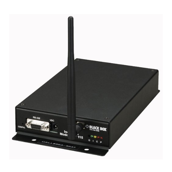
INDUSTRIAL MODEM RF115 2. Introduction The Industrial Modem RF115 (part number MDR100A-R4) is a high-performance wireless modem designed for heavy-duty industrial data communications in the 902- to 928-MHz license-free band. It uses advanced frequency-hopping technology to achieve reliable noise- and interference-immune operation. The modem operates in a number of different modes to satisfy a broad range of communications requirements. - Page 12 CHAPTER 2: Introduction You can convert the modem’s DB9 RS-232 connector to RS-485 using the RS-485 Modem Module 2-wire (part number MD3310-R2) or the RS-485 Modem Module 4-wire (part number MD3311-R2). A variety of optional RF antennas are also available (ordered separately): •...
-
Page 13: Quick Start
INDUSTRIAL MODEM RF115 3. Quick Start Follow these steps to establish full-duplex communications between a pair of new Industrial Modems: 1. Following the configuration procedures described in Chapter 4, set one of the modems to be a point-to-point slave and enter the Call Book numbers of the master and slave in each other’s call list. -
Page 14: Configuration
CHAPTER 4: Configuration 4. Configuration The modem lets you set several parameters to suit your particular application. All adjustments are done through the modem setup program, a user interface that eliminates the need for setup diskettes, DIP-switch settings, or custom software. The setup program is invoked by connecting the modem to any terminal program, setting the baud rate for that terminal to 19,200 baud, and using a small pointed object to press the Setup button on the front panel of the modem. - Page 15 INDUSTRIAL MODEM RF115 Terminal-TERMINAL.TRM File Edit Settings Phone Transfers Help MAIN MENU Version 3.0 Modem Serial Number 554-0002 Set Operation Mode Set Baud Rate Edit Call Book Edit Radio Transmission Characteristics Show Radio Statistics Edit MultiPoint Parameters (Esc) Exit Setup Enter Choice Figure 4-1.
- Page 16 CHAPTER 4: Configuration Terminal-TERMINAL.TRM File Edit Settings Phone Transfers Help MAIN MENU Version 3.0 Modem Serial Number 554-0002 Set Operation Mode Set Baud Rate Edit Call Book Edit Radio Transmission Characteristics Show Radio Statistics Edit MultiPoint Parameters (Esc) Exit Setup Enter Choice SET MODEM MODE Modem Mode is...
-
Page 17: Operation Mode Selections
INDUSTRIAL MODEM RF115 5. Operation Mode Selections (0) Point-to-Point Master As mentioned previously, the modem operates in a master/slave configuration. When designated as a master in point-to-point mode, the modem will call any or all slaves it is instructed to call in the Call Book. The master determines the settings used for all radio-transmission characteristics, regardless of the settings in the slaves and repeaters. - Page 18 CHAPTER 5: Operation Mode Selections (4) Point-to-Point Slave/Repeater Option 4 allows you to designate the modem to act as either a slave or a repeater, depending on the instructions received from the master for the specific communications session. When a modem is placed in an ideal location, this setting offers the flexibility of using that modem as an end point in the communication link (slave) or to extend the link to a point further (repeater).
- Page 19 INDUSTRIAL MODEM RF115 In mode 6: • The modem remains in slave mode until called by another modem in its Call Book or instructed to call another modem through an ATDT command. The master will disconnect when DTR goes low. •...
- Page 20 CHAPTER 5: Operation Mode Selections Table 5-1. Mode 6 Hardware Settings Modem Direct Connect Data Rate Matches baud rate on the modem Flow Control RTS/CTS Parity None Advanced Hardware Settings: Connection started by (calling PC) Always connected Connection ended by (calling PC) Always connected Connection started by (host PC) Carrier Detect...
- Page 21 INDUSTRIAL MODEM RF115 When pcANYWHERE is instructed to call a host PC corresponding to an entry that has been established with the above instructions, the following should occur: • pcANYWHERE should go into terminal mode. • A series of OKs should appear in the terminal window (one OK for each line of the script file being run).
- Page 22 CHAPTER 5: Operation Mode Selections Table 5-2. Mode 6 Script File Commands Script File Command Function Controlled ATXF_ Frequency Key ATXT_ Max Packet Size ATXD_ Min Packet Size ATXX_ Transmit Rate ATXR_ RF Data Rate ATXP_ RF Transmit Power ATDT_ Position in Call Book to Call ATD_ Allows specific RF115 Serial Number to be entered to call...
- Page 23 INDUSTRIAL MODEM RF115 4. If you want to link to a different slave, this time without using a repeater, reissue the ATXC# command, where # is either a position in the Call Book that contains no repeaters or the letter A. When the command ATXCA is issued, the modem is instructed to “Call All,”...
- Page 24 CHAPTER 5: Operation Mode Selections Table 5-3. Mode 6 Hardware Settings for Setup Mode Terminal Emulation ANSI File Transfer Protocol XMODEM Hardware Setup Name Direct Connect Hardware Setup Options: Modem Direct Connect Data Rate Matches baud rate on the RF115 Flow Control RTS/CTS Parity...
-
Page 25: Multipoint Operation
INDUSTRIAL MODEM RF115 6. Multipoint Operation In a multipoint system, a modem designated as a master is able to simultaneously be in communication with numerous slaves. In its simplest form, a multipoint network functions with the master broadcasting its messages to all slaves, and slaves responding to the master as appropriate. - Page 26 CHAPTER 6: Multipoint Operation In point-to-point operation, the modems acknowledge every data packet transmitted. In a multipoint network, transmissions from a master to the slaves are not acknowledged by the slaves. This is to prevent system overload. If the slaves acknowledged all data transmissions from the master in a large multipoint system, then all system capacity would be spent having the master listen for acknowledgments from the slaves.
- Page 27 INDUSTRIAL MODEM RF115 The repeater’s hopping pattern must also be set in a multipoint network; do this with parameter (5) Repeater Frequency. Setting this parameter is in contrast with point-to-point mode where the repeater automatically uses the master’s hopping pattern. The repeater may be programmed to either use the master’s hopping pattern (selection 0) or its own (selection 1).
-
Page 28: Network Id
CHAPTER 6: Multipoint Operation 6.2 Network ID The Network ID allows the user to set a network of units up with an ID instead of using addressing. This may be useful when a large number of slaves are in use. In a large system, if a master or repeater needs to be replaced or repeaters need to be added to add slaves, it would not be necessary to change the address in all of the units affected. -
Page 29: Multimastersync Mode
INDUSTRIAL MODEM RF115 6.3 MultiMasterSync Mode The MultiMasterSync Mode allows a configuration to have more than one master unit. This section describes the setup and operation of the MultiMasterSync mode. This mode synchronizes the transmitter with several co-located transceivers (in either point-to-point or multipoint operation), thereby eliminating the possibility of receiver overload. - Page 30 CHAPTER 6: Multipoint Operation 3. Set the “Xmit Rate” of the Grand Master to 0. RADIO PARAMETERS WARNING: Do not change parameters without reading manual FreqKey Max. Packet Size Min. Packet Size Xmit Rate RF Data Rate RF Xmit Power Slave Security RTS to CTS (Esc)
- Page 31 INDUSTRIAL MODEM RF115 5. The last parameter that needs to be set is MultiMasterSync. This parameter is set to 1 for all Submasters and left at zero (the factory default) for the Grand Master. Version 5.27 03-14-97 Standard Hop Table Modem Serial Number 571-0990 Set Operation Mode Set Baud Rate...
-
Page 32: Baud Rate Selections
CHAPTER 7: Baud Rate Selections 7. Baud Rate Selections (1) Set Baud Rate When item (1) is selected, you will be able to change the modem’s RS-232 baud rate—the communication rate between the modem and the instrument to which it is connected. -
Page 33: Call Book Selections
INDUSTRIAL MODEM RF115 8. Call Book Selections (2) Edit Call Book The Call Book allows the user to determine with which other modems a given modem will communicate, based on the serial numbers for both the master and slave. The modem’s serial number is encoded in the microprocessor and identified on the bottom label of the unit. -
Page 34: Entering Or Modifying Numbers In The Call Book
CHAPTER 8: Call Book Selections Terminal-TERMINAL.TRM File Edit Settings Phone Transfers Help DGR 900S MAIN MENU Modem Serial Number 554-0024 Set Operation Mode Set Baud Rate Edit Call Book Edit Radio Transmission Characteristics Show Radio Statistics (Esc) Exit Setup Enter Choice MODEM CALL BOOK Entry to Call is 04 Entry... -
Page 35: Programming The Call Book In Multipoint Systems
INDUSTRIAL MODEM RF115 8.2 Programming the Call Book in Multipoint Systems In a multipoint system, the slaves and repeaters are not listed in the master’s Call Book. When establishing such a system, you must have the master’s serial number in each slave’s and repeater’s Call Book, and each repeater’s serial number in the Call Book of each slave that may potentially communicate through it. -
Page 36: Radio-Transmission Parameters
CHAPTER 9: Radio-Transmission Parameters 9. Radio-Transmission Parameters (3) Edit Radio Transmission Characteristics When item (3) is selected in the main menu, the screen in Figure 9-1 appears. This screen allows you to modify the radio-transmission characteristics of the Modems. As stated in the warning, these parameters are for the sophisticated user who has a good understanding of the principles of radio data transmission. - Page 37 INDUSTRIAL MODEM RF115 (0) FreqKey Selection (0) in the Radio Parameters menu allows you to modify the hopping patterns of the modems. This is important for minimizing the interference with other RF115 modems operating in the same area. For instance, if there were 10 pairs of modems operating within a factory or refinery, changing the Frequency Key would ensure that they would not jump onto the same frequencies at the same time for the same length of time.
- Page 38 CHAPTER 9: Radio-Transmission Parameters Table 9-2. Max. Packet Size Settings RF Data Rate=2 Max. Setting Min. Setting Table 9-3. Max. Packet Size Settings RF Data Rate=3 Max. Setting Min. Setting...
- Page 39 INDUSTRIAL MODEM RF115 (3) Xmit Rate There are two settings for the Transmit Rate parameter. For normal operation, the modem should be set at Transmit Rate 1. Transmit Rate 0 is useful for estimating the signal strength. When set to Transmit Rate 0, the modems will transmit back and forth continuously, and the strength of the signal may be gauged by the Clear to Send LED.
- Page 40 CHAPTER 9: Radio-Transmission Parameters Table 9-4. Power Transmit Settings Setting Power Level Used When 0 - 3 Pair or pairs of modems operating within same or adjoining rooms. 4 - 6 Medium More than one pair of modems operating within same facility.
- Page 41 INDUSTRIAL MODEM RF115 from the slave. In point-to-multipoint mode, the master will repeat the message the number of times equal to the master packet repeat number in the multipoint Setup menu. Because the master transmit time is completely unrelated to the occurrence of any change of the RTS line, the latency time from RTS to CTS is variable.
- Page 42 CHAPTER 9: Radio-Transmission Parameters Show Radio Statistics Option (4) in the main menu allows you to view data-transmission statistics that have been gathered by the modem during the most recent session. This is useful when you want to look at signal strength, noise levels, bytes transmitted, bytes received, and the distance of the link between modems.
-
Page 43: The Modem Location
INDUSTRIAL MODEM RF115 10. The Modem Location Placement of your modem is likely to have a significant impact on its performance. In general, the rule of thumb with the modem is that the higher up the antenna, the better the communication link. You should also place the modem away from computers, telephones, answering machines, and other similar equipment. -
Page 44: Modem Radio Diagnostic Leds
CHAPTER 11: Modem Radio Diagnostic LEDs 11. Modem Radio Diagnostic LEDs The four LEDs on the modem’s front panel provide information on the operation of the modem: Power Carrier Data In (of the port) Data Out (of the port) The Power LED indicates that the modem is powered up and ready to operate. The Carrier LED indicates that the modem has established a link. -
Page 45: Using An External Antenna
INDUSTRIAL MODEM RF115 12. Using an External Antenna In certain circumstances, you might want to extend the range of the modem by using an external antenna in place of the standard whip antenna. The modem is equipped with a non-standard external jack allowing the use of a directional Yagi or omnidirectional antenna. -
Page 46: Rs-232 Pin Assignments
CHAPTER 13: RS-232 Pin Assignments 13. RS-232 Pin Assignments Table 13-1. RS-232 Pin Assignments Assignment Carrier Detect Transmit Data Receive Data Data Terminal Ready Ground Data Set Ready Ready To Send Clear to Send Ground... -
Page 47: Data Communications Settings
INDUSTRIAL MODEM RF115 14. Data Communications Settings The device to which the modem is connected should be configured to match the settings shown in Table 14-1. Table 14-1. Data Communications Parameter Settings Parameter Setting Baud Rate Match to the RF115 Data Bits Parity None... -
Page 48: Establishing Data-Communication Links With The Modem
CHAPTER 15: Establishing Data-Communication Links with the Modem 15. Establishing Data- Communication Links with the Modem The modem’s versatility allows data-communication links to be established using a variety of different configurations. This, in turn, makes it possible to extend the range of the modem and get around obstacles. - Page 49 INDUSTRIAL MODEM RF115 Figure 15-3 shows a link with two repeaters between the master and slave. With two repeaters, there is clearly more flexibility in getting around obstacles and greater total range is possible. Once again, it would be desirable to use external omnidirectional antennas with the repeaters, and attaching a Yagi to the master and slave would increase the range of the link.
- Page 50 CHAPTER 15: Establishing Data-Communication Links with the Modem Figure 15-5 depicts a standard point-to-multipoint system. In this example, any data sent from the master is broadcast to all three slaves, one of which receives it through a multipoint repeater. The data is in turn sent out of the RS-232 port of each of the three slaves.
Need help?
Do you have a question about the MDR100A-R4 and is the answer not in the manual?
Questions and answers