Table of Contents
Advertisement
Quick Links
Advertisement
Table of Contents

Related Manuals for Invacare leo


Summary of Contents for Invacare leo
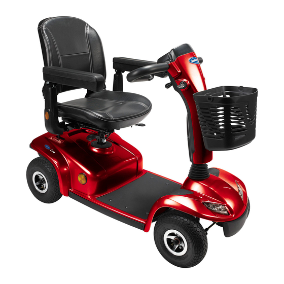
- Page 1 Yes, you can. ® Invacare® Leo Scooter User manual...
- Page 3 How can you get in touch with Invacare®? If you have any questions or need support, please contact your authorised Invacare® Dealer, who has the necessary know-how and equipment plus the special knowledge concerning your Invacare® product, and can offer you all-round satisfactory service. Should you wish to contact Invacare® directly, you can reach us in Europe at the following addresses and phone numbers.
- Page 4 +44 (0)1656 77 62 20 Pencoed uk@invacare.com Bridgend CF35 5AQ WWW: www.invacare.co.uk United Kingdom Invacare Mecc San s.r.l. +39 0445 38 00 59 Via dei Pini, 62 Fax: +39 0445 38 00 34 I - 36016 Thiene (VI) italia@invacare.com ITALIA WWW: www.invacare.it...
- Page 5 +46 (0)8 761 81 08 Fagerstagatan 9 sweden@invacare.com S-163 91 Spånga finland@invacare.com Sverige WWW: www.invacare.se Tillverkare: MÖLNDAL Invacare® Deutschland GmbH : +46 (0)31 86 36 00 Kleiststraße 49 Fax: +46 (0)31 86 36 06 D-32457 Porta Westfalica ginvacare@invacare.com Deutschland LANDSKRONA ...
-
Page 6: Table Of Contents
Table of Contents Chapter Page Introduction Important symbols in this manual ..................11 Important symbols found on the vehicle ................13 Type classification and permissible use................13 Warranty ...........................14 Life expectancy........................14 Safety notes General safety notes .......................15 Safety information with regard to care and maintenance ...........18 Safety information on electromagnetic interference ............19 Safety information on driving and freewheel mode.............20 Key features... - Page 7 Operating console Operating console arrangement ....................29 7.1.1 Status display .......................30 7.1.2 Battery charge display ....................30 Driving the Scooter .........................31 Activating and deactivating acoustic signals...............32 Diagnosis and fault repair .....................36 7.4.1 Error diagnosis......................37 Error Codes and Diagnostic Codes..................38 Adjustment facilities Moving the seat position forwards or backwards..............41 Adjusting the armrest width ....................42 Disengaging the seat to rotate it or remove it ..............43 Adjusting the seat height......................44...
- Page 8 9.2.3 Removing and fitting batteries ..................60 9.2.3.1 Removing the batteries....................61 9.2.3.2 How to handle damaged batteries correctly ............63 Charger .............................64 9.3.1 FEATURES........................64 9.3.2 CHARACTERISTICS....................64 9.3.3 INSTRUCTIONS FOR USE..................65 9.3.4 LED DISPLAY.......................65 9.3.5 TROUBLESHOOTING....................66 9.3.6 CAUTION........................66 10 Care and maintenance 10.1 Cleaning the mobility device ....................67 10.2 Inspection checks ........................68...
- Page 9 15 Inspections Performed...
-
Page 10: Introduction
The decision whether the model is suitable for the user may only be taken by medical specialists with appropriate aptitude. Invacare® or their statutory representatives can accept no liability in cases in which the mobility product has not been adapted to suit the user's handicaps. -
Page 11: Important Symbols In This Manual
This manual contains copyrighted information. It may not be reproduced or copied in whole or in part without the prior written consent of Invacare® or its authorised representative. It may also contain information that pertains to models sold only in certain countries. In this case the information will be clearly marked as pertaining to a particular country-specific version. - Page 12 RISK OF CRUSHING! This symbol warns of a risk of crushing caused by being careless with heavy components. • Always follow the instructions to avoid injury to the user or damage to the product. Wear eye protection This symbol refers to the requirement for wearing eye protection, for example when working with batteries.
-
Page 13: Important Symbols Found On The Vehicle
Important symbols found on the vehicle This product has been supplied from an environmentally aware manufacturer. This product may contain substances that could be harmful to the environment if disposed of in places (landfills) that are not appropriate according to legislation. •... -
Page 14: Warranty
Warranty The terms and conditions of the warranty are part of the general terms and conditions particular to the individual countries in which this product is sold. Life expectancy We estimate a life expectancy of five years for this product, provided it is used in strict accordance with the intended use as set out in this document and all maintenance and service requirements are met. -
Page 15: Safety Notes
Safety notes READ WELL BEFORE OPERATION! General safety notes Danger of injury if this scooter is used in any other way than the purpose described in this manual! • Adhere strictly to the instructions in this user manual! Danger of injury if the scooter is driven when your ability to drive is impaired by medication or alcohol! •... - Page 16 Danger of injury if the On/Off Button is pressed while the vehicle is in motion, due to it coming to an abrupt, sharp stop! • If you have to brake in an emergency, simply pull the handbrake until the scooter comes to a halt! Only switch the vehicle off while in motion as a last resort! Danger of injury if the scooter is transported in another vehicle with the occupant seated in it!
- Page 17 Invacare® for this purpose! Have all electrical installations done by your authorised Invacare® Dealer! Danger of technical failure and injury if unauthorised spare parts and components are used! • Only use original Invacare® spare parts, which have been approved for use with this vehicle!
-
Page 18: Safety Information With Regard To Care And Maintenance
Safety information with regard to care and maintenance Danger of accident and loss of guarantee if maintenance is insufficient! • For reasons of safety and in order to avoid accidents which result from unnoticed wear, it is important that this electric mobility product undergoes an inspection once every year under normal operating conditions (see inspection plan contained in service instructions). -
Page 19: Safety Information On Electromagnetic Interference
Safety information on electromagnetic interference This electric vehicle was successfully tested in accordance with International standards as to its compliance with Electromagnetic Interference (EMI) regulations. However, electromagnetic fields, such as those generated by radio and television transmitters, and cellular phones can influence the functions of electric vehicles. -
Page 20: Safety Information On Driving And Freewheel Mode
Safety information on driving and freewheel mode Danger of injury if the vehicle tips over! • Only ever negotiate gradients up to the maximum tilt-resistant gradient and only with the backrest in an upright position, and the seat lifter in the lowest position (if installed)! •... - Page 21 Danger of injury if the vehicle tips over! (Continued) • Never use the vehicle to transport more than one person! • Do not exceed the maximum permissible load! • When loading the vehicle, always distribute the weight evenly! Always try to keep the centre of gravity of the vehicle in the middle, and as close to the ground as possible! •...
-
Page 22: Key Features
Key features Disengaging lever Unlocking lever for sliding seat rails (front right below seat) Unlocking lever for swivelling and removing seat (left below seat) Operating console Lever for adjusting steering column inclination Keyswitch (ON/OFF) -
Page 23: The Position Of The Labels On The Product
The position of the labels on the product 1) Identification label sticker on the seat support tube... - Page 24 2) Manufacturer label on the seat support tube 3) Distributor label on the chassis at the rear 4) Battery label under the cover at the rear The symbols on the labels are explained in section "Important symbols found on the vehicle" on page 13.
-
Page 25: Driving
Driving Before driving for the first time... Before you take your first trip, you should familiarise yourself well with the operation of the vehicle and with all operating elements. Take your time to test all functions and driving modes. NOTE: If installed, make sure to properly adjust and use the postural belt each time you use the wheelchair. -
Page 26: Taking Obstacles
Taking Obstacles Your Scooter can climb obstacles and kerbs of up to 6 cm in height. CAUTION: Danger of Tipping Over! • Never approach obstacles at an angle but at 90 degrees as shown below. • Put your backrest into an upright position before climbing an obstacle. Driving up over an obstacle Correct •... -
Page 27: Driving Up And Down Gradients
Driving up and down gradients For information concerning the maximum safe slope, please see chapter "Technical specifications" starting on page 81. WARNING: Danger of tipping over! • Only ever drive downhill at a maximum of 2/3rds of the top speed! •... -
Page 28: Pushing The Scooter By Hand
Pushing the scooter by hand The motors of the scooter are equipped with automatic brakes, preventing the scooter from rolling away out of control when the power supply is switched off. When pushing the scooter, the magnetic brakes must be disengaged. Disengaging Motors Danger of the vehicle running away! •... -
Page 29: Operating Console
Operating console Operating console arrangement Battery charge display Speed controller Horn Left-hand direction indicator (switches itself off automatically after 30 seconds) Lighting Status display Warning blinker Right-hand direction indicator (switches itself off automatically after 30 seconds) Drive lever... -
Page 30: Status Display
7.1.1 Status display NOTE: The ON/OFF diode is used as a fault display (status display). Chapter "Error Codes and Diagnostic Codes" on page 38 contains an explanation of the error codes. 7.1.2 Battery charge display • All diodes illuminate: maximum driving range •... -
Page 31: Driving The Scooter
Pull the right-hand drive lever carefully to travel forwards. • Pull the left-hand drive lever carefully to travel in reverse. NOTE: The control system is programmed with standard values in the works. Your Invacare®dealer can carry out programming tailored to fit your requirements. -
Page 32: Activating And Deactivating Acoustic Signals
Caution: any changes to the drive program can affect the driving characteristics and the tipping stability of the vehicle! • Changes to the drive program may only be carried out by trained Invacare® specialist dealers! • Invacare® supplies all mobility products with a standard drive program ex-works. Invacare®... - Page 33 The electronic system must be switched off in order to activate or deactivate an acoustic signal for particular functions, and a particular keystroke combination needs to be entered when switching on again. After a signal for a particular function has been successfully activated/deactivated, a combination of LEDs on the battery charge display will blink as a confirmation.
- Page 34 The keystroke combinations and LED codes for various options are as follows: Function: Keystroke combination LED(s) Condition Acoustic signal at "Lighting" + "direction deactivated low battery capacity indicator left" D1+D2 activated Acoustic signal "Lighting" + "direction deactivated when direction indicator right" indicators actuated D3+D4 activated...
- Page 35 Activating or deactivating an acoustic signal Please proceed as follows to activate or deactivate an acoustic signal for a particular function: 1) Switch off the electronic system. 2) Enter the keystroke combination and hold. 3) Switch on the electronic system 4) Wait two seconds until the appropriate blink code is displayed on the battery charge display, then release the keys.
-
Page 36: Diagnosis And Fault Repair
Diagnosis and fault repair The electronic system offers diagnostic information to support the technician during the recognition and rectification of faults on the Scooter. If there is a fault, the status display blinks several times, pauses, then blinks again. The type of fault is displayed by the number of blinks in each group, which are also known as the "blink code". -
Page 37: Error Diagnosis
7.4.1 Error diagnosis If the Scooter shows a failure, please use the following guide to locate the fault. NOTE: Before making any diagnosis, ensure that the Scooter has been switched on at the keyswitch. If the status display is OFF: check whether the keyswitch is SWITCHED ON. -
Page 38: Error Codes And Diagnostic Codes
Error Codes and Diagnostic Codes Blink FAULT Consequence Comments code for the Scooter Battery must be Continues to • The batteries are discharged. Charge the charged drive battery as soon as possible. Battery voltage too Stops driving • The batteries are depleted. Charge batteries. - Page 39 • The electronic system has determined a motor short-circuit. Check the wiring harness for short-circuits and check the motor: Contact your Invacare® dealer. Brake failure Stops driving • Ensure that the disengaging lever is in the engaged position.
- Page 40 FAULT Consequence Comments code for the Scooter Motor voltage error Stops driving • The motor or its cabling is defective Contact your Invacare® dealer. Miscellaneous Stops driving • Contact your Invacare® dealer. internal fault Push mode / free Continues to •...
-
Page 41: Adjustment Facilities
Adjustment facilities Moving the seat position forwards or backwards The disengaging lever for adjusting the seat is located front right below the seat • Pull the lever (1) to disengage the seat. • Slide the seat forwards or backwards into the required position. -
Page 42: Adjusting The Armrest Width
Adjusting the armrest width The hand wheels for releasing the armrests are located under the seat (1). • Turn the hand wheels to loosen the fixing for the armrest. • Adjust the armrests to the required width. • Retighten the handwheels... -
Page 43: Disengaging The Seat To Rotate It Or Remove It
Disengaging the seat to rotate it or remove it The seat can be turned to one side to make getting in and out of the scooter easier. The seat is also easier to remove from this position. The lever for disengaging the seat is located under the seat (1) on the right. -
Page 44: Adjusting The Seat Height
Adjusting the seat height The seat height can be adjusted to 46, 48.5, 51, 53.5 or 56 cm. Requirements: • 2x open-ended spanners 17 mm • Remove the seat • Remove the battery and motor compartment cover. • Remove the seat pillar locking bolt using both open- ended spanners. - Page 45 • Adjust the seat height. • Reinsert the bolt and tighten.
-
Page 46: Postural Belts
Postural belts A postural belt is an option which can either be fixed to the wheelchair ex-works or can be retrofitted by your specialist dealer. If your wheelchair is fitted with a postural belt, your specialist dealer will have informed you about fitting and usage. The postural belt is used to help the wheelchair user keep an optimum sitting position. -
Page 47: Adjusting The Postural Belt Correctly
If the belt is only fastened with a bolted connection, ensure that the connection has not loosened or undone. You can find more information about maintenance work on belts in the service manual, which is available from Invacare®. -
Page 48: Fixing The Containment Belt To The Scooter
8.5.3 Fixing the containment belt to the scooter Requirements: • jaw spanner 12 mm • jaw spanner 13 mm The fixing points (1) for attaching the belt are located under the seat (the figure shows only the left hand side). - Page 49 • Take hold of the belt mounting and hold it in front of the hole in the fixing. • Position the bolt (1), screw the nut on from the other side and tighten with a jaw spanner. • Repeat the same procedure on the other side of the seat.
-
Page 50: Rollator Bracket
Rollator bracket Your scooter can be fitted with an optional rollator bracket. Only the following rollators, which have been approved by Invacare, can be transported using this bracket: • Dolomite Jazz 600 • Dolomite Legacy 600 • Invacare Banjo P452E/3 The maximum permitted rollator weight is 9 kg. -
Page 51: Attaching The Rollator
8.6.1 Attaching the rollator Dolomite Jazz 600... - Page 52 Dolomite Legacy 600 Invacare Banjo P452E/3...
-
Page 53: Removing The Rollator Bracket
8.6.2 Removing the rollator bracket • Loosen the screws (1). • Pull the rollator bracket out of the fixtures. 8.6.3 Positioning the rear reflector CAUTION! Risk of accident due to poor visibility. If you wish to use your wheelchair on public roads and a rear reflector is required by national legislation, then the rollator bracket may not cover the rear reflector. - Page 54 • Position the rear reflector as shown in the drawing.
-
Page 55: Electrical System
Electrical system Electronics protection system The vehicle's electronics are equipped with an overload-protection system. If the motors are put under considerable strain for a longer period of time (for example, when driving up a steep hill) and especially when the ambient temperature is high, then the electronic system could overheat. -
Page 56: The Main Fuse
NOTE A defective main fuse may be replaced only after checking the entire electric system. An Invacare® specialised dealer must perform the replacement. You can find information on the fuse type in chapter "Technical specifications" starting on page 81. Batteries 9.2.1... - Page 57 The batteries cannot be overcharged with the specified charger. Please use only charging devices in Class 2. This class of chargers may be left unattended during charging. All charging devices which are supplied by Invacare® comply with these requirements.
-
Page 58: Charging The Batteries
Risk of explosion and destruction of batteries if the wrong battery charger is used! • Only ever use the battery charger supplied with your vehicle, or a charger that has been approved by Invacare®. Risk of electric shock and damage to the battery charger if it gets wet! •... - Page 59 The charging socket is located on the left of the steering column Connecting the battery charger • Switch off the Scooter. • Push the protective cap on the side of the charging socket to the side. • Connect the battery charger to the Scooter. •...
-
Page 60: Removing And Fitting Batteries
9.2.3 Removing and fitting batteries WARNING: Danger of injury if the batteries are not handled correctly during assembly and maintenance work! • New batteries should be installed by authorised technicians! • Observe the warnings on the batteries! • Take into account the heavy weight of the batteries! •... -
Page 61: Removing The Batteries
9.2.3.1 Removing the batteries Requirements: • Open spanner, 11 mm. • Remove the seat. • Remove the battery and motor compartment cover. • Unplug the battery connecting plug (1). • Release the battery holder strap. • Remove the batteries. - Page 62 • Loosen the blue cable on the negative battery terminal with the open-ended spanner, and remove the cable. • Loosen the red cable battery clamp on the positive battery terminal with the open-ended spanner, and remove the cable. • Repeat the procedure for the other battery NOTE: Replacing new batteries takes place in reverse order.
-
Page 63: How To Handle Damaged Batteries Correctly
Only ever transport damaged batteries in an appropriate acid-resistant receptacle. • Wash all objects that have come into contact with acid with lots of water. Disposing of dead or damaged batteries correctly Dead or damaged batteries can be given back to your dealer or directly to Invacare®. -
Page 64: Charger
Charger 9.3.1 FEATURES 1. CHARGING LED display 2. POWER LED display 3. Mains socket 4. (115V/230V) input voltage selector switch 5. Battery charging plug 9.3.2 CHARACTERISTICS Article Battery charger (switch mode) Model 4F24040 4F24050 4F2460 Output current (DC) Charging voltage (DC) 28.8 V Trickle charging V (DC) 27.6 V... -
Page 65: Instructions For Use
Input voltage (AC) 115 Vac or 230 Vac 50/60Hz (select manually) Degree of efficiency AC-DC 80% Voltage supply Switch mode Charging process Constant current, two levels of constant voltage Battery application 24 V gel or AGM batteries (20 Ah ~ 60 Ah) Output detection 1. -
Page 66: Troubleshooting
3. If the CHARGING LED does not change from orange to green: • The battery cannot be charged correctly. It may be faulty. Please contact your Invacare dealer. 4. If the CHARGING LED changes from orange to green immediately: •... -
Page 67: Care And Maintenance
Maintenance encompasses different areas, such as everyday care and cleaning, inspection checks, repair tasks and refurbishment. NOTE: Have your vehicle checked once a year by an authorised Invacare® dealer in order to maintain it's driving safety and roadworthiness. 10.1... -
Page 68: Inspection Checks
Service Manual for this device, which can be obtained from Invacare®. That Manual, however, is intended to be used by trained and authorised service technicians, and describes tasks which are not intended to be performed by the user. - Page 69 • Before every trip Have batteries been fully charged before the daily operation? • Are all holders, screws firmly fixed, tight and safe? • Before each trip Are all electric bulbs of the lighting system (if applicable) in working order? Cleaning: •...
-
Page 70: Repair Instructions
"Technical specifications" on page 81, or consult the Service Manual, available from Invacare® (in this connection please see the addresses and phone numbers in section "How can you get in touch with Invacare®?" on page 3). In case you require assistance, please contact your Invacare® Dealer. -
Page 71: Removing/Fitting Tyres (4-Wheel Version And Rear Wheels Of 3-Wheel Version)
Fitting the tyres • Fit the tyres following the sequence described above in reverse order. • Use a new wheel safety nut. Problems removing the wheel? You may need to use a special tool. Please contact your authorised Invacare® dealer for assistance. -
Page 72: Removing/Fitting Tyres (Castor Wheel Of 3-Wheel Version)
For a description of the procedure for repairing a tyre, see section "Mending punctures" on page 11.1.2 Removing/fitting tyres (castor wheel of 3-wheel version) WARNING: Lifting the vehicle by the plastic cladding may cause damage to the cladding. • Only lift the vehicle by the chassis. Required items: •... - Page 73 Fitting the tyres • Fit the tyres following the sequence described above in reverse order. Make sure that the spacers and the washer are positioned correctly. • Use a new wheel safety nut. For a description of the procedure for repairing a tyre, see section "Mending punctures" on page...
-
Page 74: 11.1.3 Mending Punctures
Remove the wheel by tapping it gently with the rubber hammer on the rear face to carefully loosen it from the axle. Problems when removing wheel? It may be necessary to use a special tool Please ask your Invacare® dealer to help you. -
Page 75: 11.1.3.1 Repairing Punctured Tyres
11.1.3.1 Repairing punctured tyres Requirements • inner tube repair set or a new inner tube • talcum powder • open-ended spanner, 13 mm • jaw spanner 13 mm • Remove valve cap. • De-inflate the tyre by pressing in the centre valve pin. - Page 76 Did the old inner tube get wet during the repair? If you repaired the old inner tube and reused it, and it became wet during repair, it is much easier to refit it into the wheel if you powder it lightly with talcum powder. •...
-
Page 77: Dismantling The Scooter For Transport
Dismantling the Scooter for transport Please proceed as follows to dismantle the Scooter for transport: • Remove the seat • Take out batteries • Remove the drive unit Please proceed in reverse order to reassemble the Scooter. 12.1 Removing the seat The lever for releasing the seat so that the seat can be rotated and removed is located on the left under the seat (1). -
Page 78: Removing The Battery And Drive Unit
12.2 Removing the battery and drive unit • Once you have removed the seat, remove the battery and motor compartment cover panel. The cover panel is secured using a velcro band, so you only need to pull it upwards to remove 12.2.1 Removing the batteries Please see chapter "Removing and fitting batteries"... - Page 79 • Pull the disengaging lever (A) to the rear. The drive unit lock is now released. • Lift up the chassis with the seating tube. The drive unit can now be released from the chassis.
-
Page 80: Disposal
Electric components and printed circuit boards are disposed of as electronic scrap. • Exhausted or damaged batteries can be returned to your medical equipment supplier or Invacare®. • Disposal must be carried out in accordance with the respective national legal provisions. -
Page 81: Technical Specifications
Technical specifications The technical information provided hereafter applies to a standard configuration or represents maximum achievable values. These can change if accessories are added. The precise changes to these values are detailed in the sections for the respective accessories. Permissible operating and storage conditions Temperature range for operation according to ISO 7176-9: •... - Page 82 Tyres Tyre type • 10" puncture-proof Driving characteristics Speed (dependent on country - please ask your • 6 km/h dealer which speed is available in your country.) • 8 km/h Min. braking distance • 1000 mm (6 km/h) • 1500 mm (8 km/h) Max.
- Page 83 Component weights Chassis • 3-wheel: ca. 40.5 kg • 4-wheel: ca. 46 kg Seat unit • ca. 14 kg Batteries • ca. 12 kg per battery Loading Max. load • 136 kg Axle loads Max. front axle load • 85 kg Max.
-
Page 84: Inspections Performed
It is confirmed by stamp and signature that all jobs listed in the inspection schedule of the Service and Repair Instructions have been properly performed. The list of the inspection jobs to be performed can be found in the Service Manual which is available through Invacare®. Delivery Inspection... - Page 85 2513 BH, The Hague The Netherlands Distribution / Distribución / Distribucija: France, Italia, España, Portugal Invacare® Poirier SAS Route de St Roch F-37230 Fondettes France Tel: (33) (0) 247 - 62 64 66, Fax: (33) (0) 247 - 42 12 24 United Kingdom, Ireland Invacare®...
- Page 86 S-343 71 DIÖ Sweden Tel: (46) (0) 476 - 535 00, Fax: (46) (0) 476 - 535 99 Deutschland, Eastern Europe Invacare Deutschland GmbH Kleiststraße 49 32457 Porta Westfalica Deutschland Tel: (49) (0) 5731 - 754 0, Fax: (49) (0) 5731 - 754 52 191...
Need help?
Do you have a question about the leo and is the answer not in the manual?
Questions and answers