
Related Manuals for Invacare LYNX Series


Summary of Contents for Invacare LYNX Series
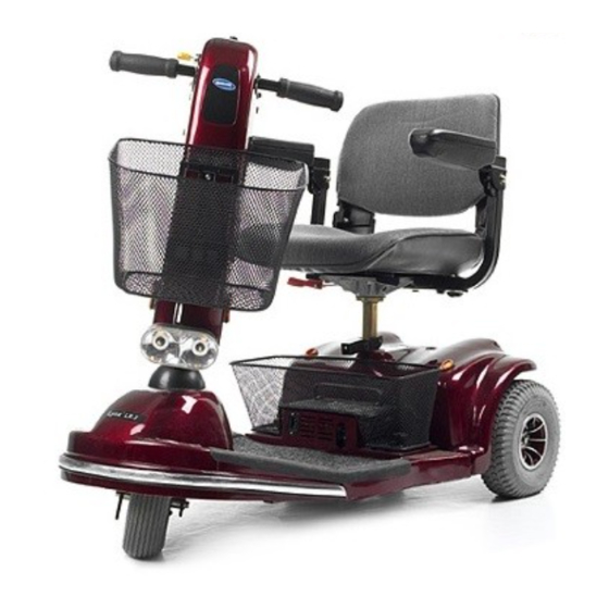
- Page 1 Service Manual LYNX /PANTHER SERIES SCOOTERS LYNX SX-3P LYNX SX-3 LYNX LX-3 LYNX LX-3 Plus PANTHER LX-4 PANTHER MX-4...
-
Page 2: Warning/Special Notes
It is the position of Invacare that users of powered scooter should be transferred into appropriate seating in vehicles for transportation and use be made of the restraints made available by the auto industry. -
Page 3: Table Of Contents
TABLE OF CONTENTS TABLE OF CONTENTS NOTE: The procedures in this manual pertain to all five (5) scooter models EXCEPT where specified. WARNING/SPECIAL NOTES ....2 PROCEDURE 7 - CONTROLLER ... 37 REMOVING/INSTALLING SPECIFICATIONS ........4 CONTROLLER ........37 PROCEDURE 1 - GENERAL GUIDELINES5 REMOVING/INSTALLING OPERATING INFORMATION .... -
Page 4: Specifications
SPECIFICATIONS SPECIFICATIONS LYNX (3-Wheel Models) PANTHER (4-Wheel Models) Plus SX-3P SX-3 LX-3 LX-3 LX-4 MX- 4 Overall Length: 43.5-inches (104 cm) 43.5-inches (104 cm) 47-inches (119 cm) 47-inches (119 cm) 47.5-inches (125 cm) 54-inches (137 cm) Overall Width: 23-inches (58 cm) 23-inches (58 cm) 25-inches (64 cm) 25-inches (64 cm) 25-inches (64 cm) 26-inches (66 cm) Ground... -
Page 5: Operating Information
Incorrect settings could cause injury to the driver, bystanders, damage to the powered scooter and surrounding property. DO NOT use parts, accessories, or adapters other than those authorized by Invacare. ELECTRICAL Check to ensure that all electrical connections are secure at all times. - Page 6 PROCEDURE 1 GENERAL GUIDELINES EMI WARNINGS (CONTINUED) The sources of radiated EMI can be broadly classified into three types: 1) Hand-held Portable transceivers (transmitters-receivers with the antenna mounted directly on the transmitting unit. Examples include: citizens band (CB) radios, "walkie talkie," security, fire, and police transceivers, cellular telephones, and other personal communication devices.
-
Page 7: Warning/Caution Label Location
GENERAL GUIDELINES PROCEDURE 1 WARNING/CAUTION LABEL LOCATION DELTA TILLER WARNING WARNING DO NOT operate without the anti- Remove key from the ignition while scooter is tip tubes installed. not in use. Otherwise, injury and/or damage to 60106X144 the scooter or surrounding property may occur. 1090105 WARNING DO NOT operate the scooter unless the tiller is in the locked... -
Page 8: Maintenance/Troubleshooting
PROCEDURE 2 SAFETY INSPECTION/MAINTENANCE/TROUBLESHOOTING This Procedure Includes the Following: Safety Inspection Checklist Maintenance NOTE: Every six (6) months take the scooter to a qualified dealer for a thorough inspection and servicing. Regular cleaning will reveal loose or worn parts and enhance the smooth operation of the scooter. To operate properly and safely, the scooter must be cared for just like any other vehicle. -
Page 9: Maintenance
SAFETY INSPECTION/MAINTENANCE/TROUBLESHOOTING PROCEDURE 2 MAINTENANCE C A U T I O N Ensure that the cover is removed from WARNING the grease nipple BEFORE operation of After ANY adjustments, repair or service the PANTHER MX-4 scooter. Otherwise, and BEFORE use, make sure that all damage to the scooter may occur. -
Page 10: Lubrication Points
PROCEDURE 2 SAFETY INSPECTION/MAINTENANCE/TROUBLESHOOTING Lubrication Points (FIGURE 2) D. For Models LYNX SX-3P, LYNX SX-3, LYNX LX-3, and LYNX LX-3 wheel Bearings 1. Every six (6) months the following components of Front Wheel. ® should be lubricated. Use a Teflon lubricant. -
Page 11: Procedure 3 - Seat
SEAT PROCEDURE 3 4. While holding the swivel release lever in the upward This Procedure Includes the Following: position, insert the NEW seat post into the seat frame. Replacing Seat Post NOTE: The seat post locks at 90° intervals. In order to ensure that the NEW seat post is locked into position, WARNING it may be necessary to rotate the seat post until an... -
Page 12: Procedure 4 - Tiller
PROCEDURE 4 TILLER 3. Repeat this procedure for the other pointed locking This Procedure Includes the Following: tab of the LED canopy. Replacing Hand Grips 4. Remove the EXISTING LED canopy and the Replacing LED Canopy EXISTING rubber gasket. Replacing Throttle Lever 5. -
Page 13: Removing/Installing Tiller Assembly
TILLER PROCEDURE 4 NOTE: To ensure the NEW throttle lever performs REMOVING/INSTALLING TILLER correctly, make certain the tab on the back of the NEW ASSEMBLY throttle lever is positioned between the two (2) ends of the spring on the potentiometer assembly. (DETAIL “A”) WARNING 5. - Page 14 PROCEDURE 4 TILLER Section A - Disassembling/Assembling 4. Separate the front frame assembly from the rear frame assembly. Refer to TRANSPORTING THE Scooter (FIGURE 4) SCOOTER in PROCEDURE 10 of the Owner’s DISASSEMBLING. Manual, part number 1090132. 1. If necessary, remove the floor basket. Refer to 5.
- Page 15 TILLER PROCEDURE 4 9. For PANTHER MX - 4, remove the brake cable 1. Remove the adjusting nut from the hand brake from the retaining tabs on the underside of the cable assembly. front frame assembly. 2. Slide the hand brake cable assembly out of the 10.
- Page 16 PROCEDURE 4 TILLER Section C - Disconnecting/Connecting 3. Disconnect the RED and BLACK cable metal connectors of the head light assembly from the Head light Assembly (FIGURE 6) RED and BLACK cable metal connectors of the DISCONNECTING. tiller wiring harness. 1.
- Page 17 TILLER PROCEDURE 4 CONNECTING (FIGURE 6). 3. Push any remaining slack in the tiller wiring har- 1. Connect the RED cable metal connector of the ness through the hole in the shroud, until the wir- head light assembly to the RED cable metal con- ing harness is on the underside of the front frame nector of the tiller wiring harness.
- Page 18 PROCEDURE 4 TILLER Section E - Disconnecting/Connecting Section F - Removing/Installing Tiller Base Handle Bar Joint From/To Front From/To Front Frame Assembly Frame Assembly (FIGURE 7) (FIGURE 8) DISCONNECTING. REMOVING. 1. Remove the two (2) bolts and self-locking nuts 1. Slowly pull the tiller wiring harness through the securing the base handle bar joint (and for the hole in the shroud assembly, until the tiller as- LYNX LX - 3 ONLY, the head light assembly) to...
-
Page 19: Removing/Installing Boot
TILLER PROCEDURE 4 DETAIL “A” REMOVING/INSTALLING BOOT (FIGURE 9) Tiller Wiring Removing Hole Harness 1. Remove the tiller assembly. Refer to REMOV- ING/INSTALLING TILLER ASSEMBLY in this Shroud procedure of this manual. Assembly 2. Remove the EXISTING boot by sliding it over the front fork with bearing assembly. -
Page 20: Wheels/Tie Rods
WARNING Installing This procedure MUST be performed by an au- 1. Place U-type plate nuts in position noted from thorized Invacare dealer or qualified techni- STEP 7 of REMOVING. cian. 2. Perform one (1) of the following: A. LYNX SX - 3, LYNX SX - 3P and LYNX LX - 3 : REMOVING/INSTALLING FRONT 1. - Page 21 SHROUD/FORK/WHEELS/TIE RODS PROCEDURE 5 5. Perform one (1) of the following: C. PANTHER MX - 4: A. LYNX SX - 3, LYNX SX - 3P, LYNX LX - 3 1. Reinstall the front head light assembly. and PANTHER LX - 4 : Refer to REMOVING/INSTALLING THE FRONT HEAD LIGHT ASSEMBLY in 1.
-
Page 22: Removing/Installing Fork
PROCEDURE 5 SHROUD/FORK/WHEELS/TIE RODS REMOVING/INSTALLING FORK 4. Secure the TOP bearing bushing by threading it into the TOP bearing housing. Torque the TOP WITH BEARING ASSEMBLY bearing bushing between 26 - 39 in./lbs. (FIGURE 2) CAUTION NOTE: This procedure applies to the LYNX SX - 3, DO NOT overtighten the bearing gap nut. -
Page 23: Removing/Installing Front Axle Assembly
SHROUD/FORK/WHEELS/TIE RODS PROCEDURE 5 REMOVING/INSTALLING FRONT 2. Secure the front axle assembly to the front frame using the washer and self-locking nut. Torque the AXLE ASSEMBLY locking nut between 108 - 135 in./lbs. NOTE: This procedure applies to the PANTHER LX 3. - Page 24 PROCEDURE 5 SHROUD/FORK/WHEELS/TIE RODS Panther MX - 4 (FIGURE 4) CAUTION DO NOT overtighten the self-locking nut secur- REMOVING. ing the tie rod assembly to the right front axle. 1. Remove the tiller assembly. Refer to REMOV- Otherwise, damage to the tie rod assembly ING/INSTALLING TILLER ASSEMBLY in PRO- may occur.
-
Page 25: Replacing Tie Rod Assembly
SHROUD/FORK/WHEELS/TIE RODS PROCEDURE 5 REPLACING TIE ROD ASSEMBLY 15. Slide the NEW steering shaft with the NEW BOTTOM bearing and the NEW BOTTOM bear- NOTE: This procedure applies to the PANTHER LX ing bushing into the front frame assembly. - 4 and the PANTHER MX - 4 ONLY. 16. - Page 26 PROCEDURE 5 SHROUD/FORK/WHEELS/TIE RODS Bearing Gap Nut (STEPS 8 and 18) Hex Cap Screws (STEPS 6 and 20) Top Bearing Bushing (STEPS 9 and 17) Top Bearing (STEPS 10 and 16) Steering Shaft U - Plate Top Bearing Housing (STEPS 11 and 15) (STEPS 7 and 19) (STEPS 12 and 13) Front Frame Assembly...
- Page 27 SHROUD/FORK/WHEELS/TIE RODS PROCEDURE 5 19. Secure the NEW tie rod assembly onto the right CAUTION front axle using the NEW washer and self-lock- DO NOT overtighten the bearing gap nut. Oth- ing nut. Torque the NEW self-locking nut between erwise, damage to the tie rod assembly may 139 - 165 in./lbs.
-
Page 28: Removing/Installing Small Tie Rods
PROCEDURE 5 SHROUD/FORK/WHEELS/TIE RODS REMOVING/INSTALLING SMALL CAUTION DO NOT overtighten the self-locking nuts secur- TIE RODS ing the small tie rod to the right front wheel axle. NOTE: This procedure applies to the PANTHER LX Otherwise, damage to the tie rod may occur. - 4 and the PANTHER MX - 4 ONLY. - Page 29 SHROUD/FORK/WHEELS/TIE RODS PROCEDURE 5 Panther MX - 4 (FIGURE 8) 4. Align the mounting hole in the small tie rod with the mounting hole in the steering shaft. REMOVING. 5. Position the small spacer between the small tie 1. Remove the tiller assembly. Refer to REMOV- rod and the steering shaft.
-
Page 30: Removing/Installing Large Tie Rods
PROCEDURE 5 SHROUD/FORK/WHEELS/TIE RODS REMOVING/INSTALLING LARGE 3. Position the mounting bolt on the large tie rod in the mounting hole in the right front wheel axle. TIE RODS CAUTION NOTE: This procedure applies to the PANTHER LX DO NOT overtighten the self-locking nuts se- - 4 and the PANTHER MX - 4 ONLY. - Page 31 SHROUD/FORK/WHEELS/TIE RODS PROCEDURE 5 Panther MX - 4 (FIGURE 10) 4. Position the EXISTING spacer between the tie rod and the left front wheel axle. REMOVING. 5. Align the mounting hole in the large tie rod with 1. Remove the tiller assembly. Refer to REMOV- the mounting hole in the left front wheel axle.
-
Page 32: Brake
PROCEDURE 6 TRANSAXLE/MOTOR/BRAKE 9. Remove the two (2) bolts, washers, spring wash- This Procedure Includes the Following: ers and self-locking nuts securing the bracket and Removing/InstallingTransaxle Assembly rubber spacer located near the transaxle hous- Replacing Motor/Brake Assembly ing to the rear frame assembly. Replacing Brake Release Lever Assembly 10. - Page 33 TRANSAXLE/MOTOR/BRAKE PROCEDURE 6 10. Reinstall the rear shroud. Refer to REMOVING/IN- 8. Reinstall the rear wheels. Refer to REMOVING/IN- STALLING THE REAR SHROUD in PROCEDURE STALLING THE REAR WHEELS in PROCEDURE 9 of the Owner’s Manual, part number 1090132. 9 of the Owner’s Manual, part number 1090132. 11.
- Page 34 PROCEDURE 6 TRANSAXLE/MOTOR/BRAKE Panther MX - 4 (FIGURE 2) CAUTION DO NOT overtighten the two (2) screws secur- REMOVING. ing the bracket and rubber spacer to the rear 1. Remove the seat. Refer to REMOVING/IN- frame assembly. Otherwise, damage to the STALLING THE SEAT in PROCEDURE 5 of the bracket and rubber spacer may occur.
-
Page 35: Replacing Motor/Brake Assembly
TRANSAXLE/MOTOR/BRAKE PROCEDURE 6 15. Reinstall the seat. Refer to REMOVING/IN- REPLACING MOTOR/BRAKE STALLING THE SEAT in PROCEDURE 5 of the ASSEMBLY (FIGURE 3) Owner’s Manual, part number 1090132. Remove the transaxle assembly. Refer to RE- MOVING/INSTALLING TRANSAXLE ASSEM- Top Bolt BLY in PROCEDURE 6 of this manual. -
Page 36: Replacing Brake Release Lever Assembly
PROCEDURE 6 TRANSAXLE/MOTOR/BRAKE REPLACING BRAKE RELEASE 3. Remove the socket screw and the bolt socket securing the brake release lever to motor/brake LEVER ASSEMBLY (FIGURE 4) assembly. For All Models EXCEPT Panther MX - 4 4. Remove the brake release lever. 1. -
Page 37: Procedure 7 - Controller
CONTROLLER PROCEDURE 7 CONNECTING. This Procedure Includes the Following: 1. Connect the following (FIGURE 1): Removing/Installing Controller A. The RED and WHITE connectors to the slot Removing/Installing Controller Harnesses marked “B+” on the controller. Replacing Circuit Breaker B. The BLACK and GREEN connectors to the slot marked “B-”... - Page 38 PROCEDURE 7 CONTROLLER INSTALLING. 2. Reinstall the transaxle assembly. Refer to RE- MOVING/INSTALLING TRANSAXLE ASSEM- 1. Perform one of the following: BLY in the PROCEDURE 6 of this manual. A. LYNX SX - 3 and LYNX SX - 3P (FIGURE 2): 3.
-
Page 39: Removing/Installing Controller Harnesses
CONTROLLER PROCEDURE 7 REMOVING/INSTALLING LYNX SX - 3P AND LYNX SX - 3 Short CONTROLLER HARNESSES Screws Washer Lynx SX - 3P And Lynx SX - 3 (FIGURE 3) Controller Washer REMOVING. 1. Disconnect the controller wires. Refer to DISCON- NECTING/CONNECTING CONTROLLER Retaining WIRES in this procedure of the manual. - Page 40 PROCEDURE 7 CONTROLLER 5. Connect the RED and BLACK connectors of the 8. Connect the BLUE connector of the tiller wiring power wiring harnesses to the RED and BLACK harness to the BLUE connector of the controller connectors of the controller wiring harnesses. wiring harness.
- Page 41 CONTROLLER PROCEDURE 7 7. Cut the cable tie securing the transaxle wiring har- 5. Connect the WHITE connector of the transaxle ness to the rear frame. assembly wiring harness to the WHITE connec- tor of the controller wiring harness. 8. Cut the cable tie securing the power wiring har- NOTE: Be sure the metal connectors are in the nesses to the rear frame.
- Page 42 PROCEDURE 7 CONTROLLER Panther MX - 4 (FIGURE 5) 9. Cut the cable tie securing the tiller wiring harness to the rear frame. REMOVING. 10. Cut the cable tie securing the main control hous- 1. Disconnect the controller wires. Refer to DIS- ing wiring harnesses to the retaining tab.
-
Page 43: Replacing Circuit Breaker
CONTROLLER PROCEDURE 7 8. Connect the metal connectors of the power wir- 10. Reinstall the rear shroud. Refer to REMOVING/IN- ing harnesses to the metal connectors of the cir- STALLING THE REAR SHROUD in PROCEDURE cuit breaker. 9 of the Owner’s Manual, part number 1090132. 9. -
Page 44: Parts - Lynx Sx - 3P
PROCEDURE 8 REPLACEMENT PARTS - LYNX SX - 3P Self-locking Mounting This Procedure Includes the Following: nuts Holes Replacing Tiller Charge Port Cover Tiller Charger WARNING Port Cover After ANY adjustments, repair or service and BEFORE use, make sure that all attaching hard- ware is tightened securely - otherwise injury or damage may occur. -
Page 45: Procedure 9 - Replacement Parts - Lynx - Lx 3
REPLACEMENT PARTS - LYNX LX - 3 PROCEDURE 9 This Procedure Includes the Following: Removing/Installing Head light Assembly Tiller WARNING Wiring After ANY adjustments, repair or service and Harness BEFORE use, make sure that all attaching hard- ware is tightened securely - otherwise injury or Head damage may occur. -
Page 46: Procedure 10 - Replacement Parts - Panther Lx - 4
PROCEDURE 10 REPLACEMENT PARTS - PANTHER LX - 4 5. Reposition the plastic guards over the metal con- This Procedure Includes the Following: nectors on the RED and BLACK cables con- Removing/Installing Head Light Assembly necting the tiller wiring harness to the head light assembly (DETAIL “A”). -
Page 47: Replacing Tiller Charger Port Cover
REPLACEMENT PARTS - PANTHER LX - 4 PROCEDURE 10 REPLACING TILLER CHARGER 5. Secure the NEW cushion to the front frame as- sembly using the two (2) NEW mounting screws, PORT COVER (FIGURE 2) spring washers and washers. Securely tighten. NOTE: Save the two (2) mounting screws and self- 6. -
Page 48: Procedure 11 - Replacement Parts - Panther Mx - 4
PROCEDURE 11 REPLACEMENT PARTS - PANTHER MX - 4 8. Remove the two (2) self-locking nuts, three (3) This Procedure Includes the Following: washers, spring washer, spring and the long screw Removing/Installing Head Light Assembly securing the bottom of the head light assembly to the bracket on the front frame assembly. - Page 49 REPLACEMENT PARTS - PANTHER MX - 4 PROCEDURE 11 13. Position the rubber spacer and the front bumper 15. Return the front frame assembly to the upright so that the mounting holes in the rubber spacer position. and the front bumper align with the mounting 16.
-
Page 50: Replacing Tail Light Assembly
PROCEDURE 11 REPLACEMENT PARTS - PANTHER MX - 4 Locking Tabs REPLACING TAIL LIGHT (Squeeze Together) ASSEMBLY (FIGURE 2) 1. Remove the rear shroud. Refer to REMOVING/ Cables Tail Light INSTALLING THE REAR SHROUD in PROCE- Assembly DURE 9 of the Owner’s Manual, part number Rubber 1090132. -
Page 51: Replacing Disc Brake Assembly
REPLACEMENT PARTS - PANTHER MX - 4 PROCEDURE 11 Plastic 8. Secure the NEW disc brake assembly to the Tail Light Guards transaxle assembly using the four (4) NEW hex - Cable cap screws and spring washers. Torque the hex cap screws between 43 - 61 in./lbs. -
Page 52: Replacing Hand Brake Assembly
PROCEDURE 11 REPLACEMENT PARTS - PANTHER MX - 4 4. Disconnect the hand brake cable assembly. Re- 15. Reinstall the seat. Refer to REMOVING/IN- fer to REMOVING/INSTALLING TILLER AS- STALLING THE SEAT in PROCEDURE 5 of the SEMBLY, SECTION “B” - DISCONNECTING/ Owner’s Manual, part number 1090132. -
Page 53: Removing/Installing Front Shock Absorbers
REPLACEMENT PARTS - PANTHER MX - 4 PROCEDURE 11 14. Install the NEW bolt securing the NEW hand REMOVING/INSTALLING FRONT brake assembly to the handle bar. Refer to DE- SHOCK ABSORBERS (FIGURE 7) TAIL “A”. Securely tighten. Removing 1. Separate the front frame assembly from the rear Hand frame assembly. -
Page 54: Removing/Installing Rear Shock Absorbers
PROCEDURE 11 REPLACEMENT PARTS - PANTHER MX - 4 Installing 5. If necessary, repeat this procedure for the other front shock absorber. NOTE: When installing the bolts for the rear shock 6. Return the front frame assembly to the upright absorber, the TOP and BOTTOM bolts should be position. - Page 55 REPLACEMENT PARTS - PANTHER MX - 4 PROCEDURE 11 Bolt Rear Shock Bottom Absorber Bolt Rear Frame Assembly FIGURE 8 - REMOVING/INSTALLING REAR SHOCK ABSORBER...
-
Page 56: Procedure 12 - Options
PROCEDURE 12 OPTIONS 8. While perfoming STEP 7, pull the YELLOW wire This Procedure Includes the Following: out from the back of the YELLOW or WHITE Preparing the Scooter for Left Hand connector (depending on scooter model) of the Operation tiller wiring harness. - Page 57 OPTIONS PROCEDURE 12 NOTE: The NEW Forward/Reverse sticker is also 17. Position the NEW Forward/Reverse sticker available as a purchase part. OVER the EXISTING Forward/Reverse sticker on the control panel (DETAIL “A”). (ALL MODELS EXCEPT THE PANTHER MX - 4) Yellow Wire Male Pin Plastic Tang...
-
Page 58: Notes
NOTES NOTES ____________________________________________________________________________ ____________________________________________________________________________ ____________________________________________________________________________ ____________________________________________________________________________ ____________________________________________________________________________ ____________________________________________________________________________ ____________________________________________________________________________ ____________________________________________________________________________ ____________________________________________________________________________ ____________________________________________________________________________ ____________________________________________________________________________ ____________________________________________________________________________ ____________________________________________________________________________ ____________________________________________________________________________ ____________________________________________________________________________ ____________________________________________________________________________ ____________________________________________________________________________ ____________________________________________________________________________ ____________________________________________________________________________ ____________________________________________________________________________ ____________________________________________________________________________ ____________________________________________________________________________ ____________________________________________________________________________ ____________________________________________________________________________ ____________________________________________________________________________ ____________________________________________________________________________ ____________________________________________________________________________ ____________________________________________________________________________ ____________________________________________________________________________ ____________________________________________________________________________ ____________________________________________________________________________ ____________________________________________________________________________ ____________________________________________________________________________ ____________________________________________________________________________ ____________________________________________________________________________ ____________________________________________________________________________ ____________________________________________________________________________ ____________________________________________________________________________ ____________________________________________________________________________ ____________________________________________________________________________ ____________________________________________________________________________... -
Page 59: Warranty
This warranty gives you specific legal rights and you may also have other legal rights which vary from state to state. Invacare warrants this product to be free from defects in materials and workmanship for a period of eighteen (18) months on electrical and transaxle and three (3) years on frame from date of purchase. - Page 60 Invacare Corporation Canada...
Need help?
Do you have a question about the LYNX Series and is the answer not in the manual?
Questions and answers