Advertisement
Table of Contents
- 1 Table of Contents
- 2 Warning Decal Placement
- 3 Important Precautions
- 4 Before You Begin
- 5 Part Identification Chart
- 6 Assembly
- 7 Operation and Adjustment
- 8 How to Fold and Move the Treadmill
- 9 Troubleshooting
- 10 Exercise Guidelines
- 11 Part List
- 12 Exploded Drawing
- 13 Ordering Replacement Parts
- 14 Limited Warranty
- Download this manual
www.workoutwarehouse.com
USER'S MANUAL
Model No. GGTL39610.0
Serial No.
Write the serial number in the space
above for reference.
Serial Number
Decal
QUESTIONS?
If you have questions, or if parts
are damaged or missing, DO NOT
CONTACT THE STORE; please
contact Customer Care.
IMPORTANT: Please register this
product (see the limited warranty
on the back cover of this manual)
before contacting Customer Care.
CALL TOLL-FREE:
1-877-776-4777
Mon.–Fri., 6 a.m.–6 p.m. MT
Sat. 8 a.m.–4 p.m. MT
ON THE WEB:
www.workoutwarehouse.com
CAUTION
Read all precautions and instruc-
tions in this manual before using
this equipment. Keep this manual
for future reference.
Advertisement
Table of Contents

Related Manuals for Gold's Gym GGTL39610.0


Summary of Contents for Gold's Gym GGTL39610.0
- Page 1 USER’S MANUAL Model No. GGTL39610.0 Serial No. Write the serial number in the space above for reference. Serial Number Decal QUESTIONS? If you have questions, or if parts are damaged or missing, DO NOT CONTACT THE STORE; please contact Customer Care.
-
Page 2: Table Of Contents
TABLE OF CONTENTS WARNING DECAL PLACEMENT ............. . .2 IMPORTANT PRECAUTIONS . -
Page 3: Important Precautions
IMPORTANT PRECAUTIONS WARNING: To reduce the risk of serious injury, read all important precations and in- structions in this manual and all warnings on your treadmill before using your treadmill. ICON as- sumes no responsibility for personal injury or property damage sustained by or through the use of this product. - Page 4 20. Never leave the treadmill unattended while 24. Inspect and properly tighten all parts of the it is running. Always remove the key, unplug treadmill regularly. the power cord, and press the power switch DANGER : Always unplug the power into the off position when the treadmill is not cord immediately after use, before clean- in use.
-
Page 5: Before You Begin
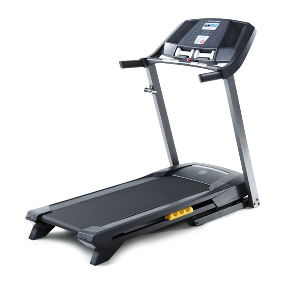
BEFORE YOU BEGIN Thank you for selecting the new GOLD’S GYM this manual, please see the front cover of this manual. ® TRAINER 410 treadmill. The TRAINER 410 treadmill To help us assist you, note the product model number provides an impressive selection of features designed and serial number before contacting us. -
Page 6: Part Identification Chart
PART IDENTIFICATION CHART Use the drawings below to identify small parts used for assembly. The number in parentheses below each draw- ing is the key number of the part, from the PART LIST near the end of this manual. The number following the key number is the quantity used for assembly. -
Page 7: Assembly
ASSEMBLY • To hire a service technician to assemble this prod- is lubricant on top of the walking belt, wipe it off uct in your home, call 1-800-445-2480. with a soft cloth and a mild, non-abrasive cleaner. • Assembly requires two persons. • To identify small parts, see page 6. - Page 8 3. Identify the Right Upright (76), which is marked “Right.” Have a second person hold the Right Upright near the Base (74). See the inset drawing. Tie the wire tie in the Right Upright (76) securely around the end of the Upright Wire (63).
- Page 9 5. Identify the Right Handrail (64), which is marked “Right.” Have a second person hold the Right Handrail near the Right Upright (76). Route the Upright Wire (63) into the bottom of the Right Handrail (64) and out of the hole in the Right Handrail.
- Page 10 7. Remove the four screws (D) from the Left and Right Handrails (59, 64). Discard the screws. 8. Attach the Console Crossbar (61) to the Left and Right Uprights (66, 76) with four #10 x 3/4" Screws (8) and four #10 Star Washers (23). Start all four Screws, and then tighten them.
- Page 11 9. With the help of a second person, hold the con- sole assembly near the Right Handrail (64). Connect the Upright Wire (63) to the console Console wire. See the inset drawing. The connectors Assembly should slide together easily and snap into place.
- Page 12 11. Note: There may be two screws (E) preattached to the Left Upright (66). If so, remove and dis- card the screws. Attach the Latch Housing (67) to the Left Upright (66) with two #10 x 3/4" Screws (8); start both Screws, and then tighten them.
-
Page 13: Operation And Adjustment
OPERATION AND ADJUSTMENT HOW TO CONNECT THE POWER CORD nominal 120-volt circuit capable of carrying 15 or more amps. To avoid overloading the circuit, do Use a Surge Suppressor not plug other electrical devices, except for low- power devices such as cell phone chargers, into Your treadmill, like other electronic equipment, can be the surge suppressor or into an outlet on the same circuit. - Page 14 CONSOLE DIAGRAM FEATURES OF THE CONSOLE To turn on the power, see page 15. To use the man- ual mode, see page 15. To use a preset workout, see The treadmill console offers a selection of features page 17. To use the information mode, see page 18. designed to make your workouts more effective.
- Page 15 HOW TO TURN ON THE POWER HOW TO USE THE MANUAL MODE IMPORTANT: If the treadmill has been exposed to 1. Insert the key into the console. cold temperatures, allow it to warm to room tem- perature before turning on the power. If you do not See HOW TO TURN ON THE POWER at the left.
- Page 16 4. Change the incline of the treadmill as desired. burned, or the speed of the walking belt. Press the Priority Display button repeatedly until the upper To change the incline of the treadmill, press the display shows the information that you are most Incline increase and decrease buttons or one of interested in viewing.
- Page 17 HOW TO USE A PRESET WORKOUT When you use a weight- loss workout, the con- 1. Insert the key into the console. sole will prompt you to use the dumbbells for See HOW TO TURN ON THE POWER on page 15. a full-body crosstrain- ing workout.
- Page 18 THE INFORMATION MODE power switch into the reset position, and insert the key into the console. However, when you remove the The console features an information mode that keeps key, the displays will remain lit, although the buttons track of treadmill usage information and allows you to will not function.
-
Page 19: How To Fold And Move The Treadmill
HOW TO FOLD AND MOVE THE TREADMILL HOW TO FOLD THE TREADMILL HOW TO MOVE THE TREADMILL Before folding the treadmill, adjust the incline to Before moving the treadmill, fold it as described at the the lowest position. If you do not do this, you may left. -
Page 20: Troubleshooting
TROUBLESHOOTING Most treadmill problems can be solved by following c. Remove the key from the console, and then the simple steps below. Find the symptom that reinsert it. applies, and follow the steps listed. If further assis- tance is needed, see the front cover of this manual. d. - Page 21 Locate the Reed Switch (33) and the Magnet (32) b. If the walking belt is overtightened, treadmill per- on the right side of the Pulley (31). Turn the Pulley formance may decrease and the walking belt may until the Magnet is aligned with the Reed Switch. become damaged.
- Page 22 SYMPTOM: The walking belt is off-center or slips b. If the walking belt slips when walked on, first re- when walked on move the key and UNPLUG THE POWER CORD. Using the hex key, turn both idler roller screws a. If the walking belt is off-center, first remove the clockwise, 1/4 of a turn.
-
Page 23: Exercise Guidelines
EXERCISE GUIDELINES Burning Fat—To burn fat effectively, you must exer- WARNING: cise at a low intensity level for a sustained period of Before beginning this time. During the first few minutes of exercise, your or any exercise program, consult your physi- body uses carbohydrate calories for energy. -
Page 24: Part List
PART LIST Model No. GGTL39610.0 R0512A Key No. Qty. Description Key No. Qty. Description #8 x 1/2" Ground Screw Hex Key 3/8" x 3 1/4" Screw 5/32" Hex Key 3/8" Star Washer Right Rear Foot #8 x 3/4" Screw Not Used 5/16"... -
Page 25: Exploded Drawing
EXPLODED DRAWING A Model No. GGTL39610.0 R0512A... - Page 26 EXPLODED DRAWING B Model No. GGTL39610.0 R0512A...
- Page 27 EXPLODED DRAWING C Model No. GGTL39610.0 R0512A 10 75...
-
Page 28: Ordering Replacement Parts
ORDERING REPLACEMENT PARTS To order replacement parts, please see the front cover of this manual. To help us assist you, be prepared to provide the following information when contacting us: • the model number and serial number of the product (see the front cover of this manual) • the name of the product (see the front cover of this manual) • t he key number and description of the replacement part(s) (see the PART LIST and the EXPLODED DRAWING near the end of this manual) LIMITED WARRANTY IMPORTANT: You must register this product within 30 days of the purchase date to avoid added fees for service needed under warranty.
Need help?
Do you have a question about the GGTL39610.0 and is the answer not in the manual?
Questions and answers
My treadmill is not running on speed
Your Gold's Gym treadmill GGTL39610.0 may not be running at speed due to the following reasons:
1. Demo Mode Enabled – If the displays light up as soon as you plug in the power cord and press the power switch, the treadmill may be in demo mode. To turn it off, hold down the Stop button for a few seconds. If the displays remain lit, refer to the Information Mode settings.
2. Key Not Inserted – Ensure that the key is properly inserted into the console, as the treadmill will not operate without it.
3. Incorrect Speed Settings – Press the Go button, Speed increase button, or one of the ten numbered MPH buttons to start the walking belt. If the speed does not increase, try adjusting the speed using the Speed increase and decrease buttons.
4. Segment Settings in a Programmed Workout – If you are using a programmed workout, check if the current segment has a lower speed setting. The treadmill adjusts speed automatically based on the workout program.
If the issue persists, further troubleshooting may be required.
This answer is automatically generated
Incline stuck
Is this treadmill compatible with any app? How to save a custom program