Advertisement
Table of Contents
- 1 Table of Contents
- 2 Warning Decal Placement
- 3 Important Precautions
- 4 Before You Begin
- 5 Assembly
- 6 Operation and Adjustment
- 7 How to Fold and Move the Treadmill
- 8 Troubleshooting
- 9 Exercise Guidelines
- 10 Part List
- 11 Exploded Drawing
- 12 Ordering Replacement Parts
- 13 Limited Warranty
- Download this manual
www.workoutwarehouse.com
USERʼS MANUAL
Model No. GGTL07819.0
Serial No.
Write the serial number in the space
above for reference.
Serial Number
Decal
QUESTIONS?
If you have questions, or if parts are
damaged or missing, DO NOT CON-
TACT THE STORE; please contact
Customer Care.
IMPORTANT: Please register this
product (see the limited warranty
on the back cover of this manual)
before contacting Customer Care.
1-877-776-4777
CALL TOLL-FREE:
Mon.–Fri. 6 a.m.–6 p.m. MT
Sat. 8 a.m.–4 p.m. MT
ON THE WEB:
www.workoutwarehouse.com
CAUTION
Read all precautions and instruc-
tions in this manual before using
this equipment. Save this manual
for future reference.
Advertisement
Table of Contents

Subscribe to Our Youtube Channel
Related Manuals for Gold's Gym MAXX 685T


Summary of Contents for Gold's Gym MAXX 685T
- Page 1 www.workoutwarehouse.com USERʼS MANUAL Model No. GGTL07819.0 Serial No. Write the serial number in the space above for reference. Serial Number Decal QUESTIONS? If you have questions, or if parts are damaged or missing, DO NOT CON- TACT THE STORE; please contact Customer Care.
-
Page 2: Table Of Contents
Apply the decal in the location shown. Note: The decals may not be shown at actual size. GOLD'S GYM is a registered trademark of Gold's Gym International, Inc. This product is manufactured and distributed under license from Gold's Gym Merchandising, Inc. -
Page 3: Important Precautions
IMPORTANT PRECAUTIONS WARNING: To reduce the risk of serious injury, read all important precautions and in- structions in this manual and all warnings on your treadmill before using your treadmill. ICON as- sumes no responsibility for personal injury or property damage sustained by or through the use of this product. - Page 4 20. Never leave the treadmill unattended while it 24. Inspect and properly tighten all parts of the is running. Always remove the key, unplug treadmill regularly. DANGER: the power cord, and switch the reset/off cir- cuit breaker to the off position when the Always unplug the power treadmill is not in use.
-
Page 5: Before You Begin
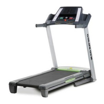
BEFORE YOU BEGIN Thank you for selecting the revolutionary GOLDʼS ing this manual, please see the front cover of this man- MAXX 685T treadmill. The MAXX 685T treadmill ual. To help us assist you, note the product model ® offers an impressive selection of features designed to number and serial number before contacting us. -
Page 6: Assembly
ASSEMBLY To hire an authorized service technician to assemble the treadmill, call 1-800-445-2480. Assembly requires two persons. Set the treadmill in a cleared area and remove all packing materials. Do not dispose of the packing materials until assembly is completed. Note: The underside of the treadmill walking belt is coated with high-performance lubricant. - Page 7 1. Make sure that the power cord is unplugged. Hole With the help of a second person, carefully tip the treadmill onto its left side. Partially fold the Frame (48) so that the treadmill is more stable; do not fully fold the Frame yet. Cut the shipping tie securing the Wire Harness (91) to the Base (96).
- Page 8 4. Hold a Bolt Spacer (95) inside the lower end of the Right Upright (92). Insert a 3/8" x 4" Bolt (8) with a 3/8" Star Washer (11) into the Right Upright and the Bolt Spacer. Repeat this step with a second Bolt Spacer (95), 3/8" x 4" Bolt (8), and 3/8"...
- Page 9 6. Hold a Bolt Spacer (95) inside the lower end of the Left Upright (77). Insert a 3/8" x 4" Bolt (8) with a 3/8" Star Washer (11) into the Left Upright and the Bolt Spacer. Repeat this step with a second Bolt Spacer (95), 3/8" x 4" Bolt (8), and 3/8"...
- Page 10 9. Set the console assembly face down on a soft surface to avoid scratching the console assem- bly. Remove the two #8 x 3/4" Screws (1). Lift off the Pulse Bar (90). Save the Pulse Bar and the two Screws for assembly steps 10 and Console Assembly 10.
- Page 11 12. Set the console assembly on the Left and Right Uprights (77, 92). Be careful not to pinch any Console Assembly wires. Attach the console assembly to the Pulse Bar (90) with six #8 x 3/4" Screws (1). Start all six Screws before firmly tightening any of them.
- Page 12 15. Raise the Frame (48) to the position shown. Have a second person hold the Frame until this step is completed. Orient the Storage Latch (45) so that the large barrel and the Latch Knob (46) are in the posi- tions shown.
-
Page 13: Operation And Adjustment
OPERATION AND ADJUSTMENT THE PRE-LUBRICATED WALKING BELT tric shock. This product is equipped with a cord having an equipment-grounding conductor and a grounding plug. Plug the power cord into a surge suppressor, Your treadmill features a walking belt coated with high- performance lubricant. - Page 14 CONSOLE DIAGRAM Clip FEATURES OF THE CONSOLE quick program, see page 17. To create and use your own quick program, see pages 18 and 19. To use the information mode, see page 20. The treadmill console offers an impressive array of features designed to help you get the most from your IMPORTANT: If there is a sheet of clear plastic on workouts.
- Page 15 HOW TO TURN ON THE POWER by pressing a Programs button repeatedly until a track appears in the center of the display. IMPORTANT: If the treadmill has been exposed to cold temperatures, allow it to warm to room tem- 3. Start the walking belt. perature before turning on the power.
- Page 16 5. Follow your progress with the matrix and the To review specific information, press the Display displays. button repeatedly until the displays show the infor- mation that you are most interested in viewing. The matrix— 6. Measure your heart rate if desired. When the man- ual mode is se- lected, the matrix...
- Page 17 HOW TO USE A PERSONAL TRAINER QUICK resents the current segment of the program. The PROGRAM height of the flashing segment indicates the speed setting for the current segment. At the end of each 1. Insert the key into the console. segment, a series of tones will sound and the next segment of the profile will begin to flash.
- Page 18 HOW TO CREATE YOUR OWN QUICK PROGRAM and Power Incline buttons. Every few 1. Insert the key into the console. times a Quick Speed button is Current Segment See HOW TO TURN ON THE POWER on page pressed, an addi- tional indicator will appear or disap- 2.
- Page 19 HOW TO USE YOUR OWN QUICK PROGRAM and incline setting is programmed for the next seg- ment, the speed or incline setting will flash in the 1. Insert the key into the console. display to alert you. The treadmill will then auto- matically adjust to the speed and/or incline setting See HOW TO TURN ON THE POWER on page for the next segment.
- Page 20 THE INFORMATION MODE An “E” for English miles or an “M” for metric kilometers The console features an information mode that keeps will appear in the Quick track of the total number of miles that the walking belt Speed display. Press the has moved and the total number of hours that the Speed increase button to treadmill has been operated.
-
Page 21: How To Fold And Move The Treadmill
HOW TO FOLD AND MOVE THE TREADMILL HOW TO FOLD THE TREADMILL FOR STORAGE Before folding the treadmill, adjust the incline to the lowest position. If you do not do this, you may damage the treadmill when you fold it. Remove the key and unplug the power cord. -
Page 22: Troubleshooting
TROUBLESHOOTING Most treadmill problems can be solved by following the steps below. Find the symptom that applies, and follow the steps listed. If further assistance is needed, please see the front cover of this manual. PROBLEM: The power does not turn on SOLUTION: a. - Page 23 Remove the three #8 x 3/4" Screws (1) and care- fully pivot the Motor Hood (58) off. Locate the Reed Switch (65) and the Magnet (40) on the left side of the Pulley (41). Turn the Pulley until the Magnet is aligned with the Reed Switch. 1/8 in.
- Page 24 PROBLEM: The walking belt is off-center or slips when walked on SOLUTION: a. If the walking belt is off-center, first remove the key and UNPLUG THE POWER CORD. If the walking belt has shifted to the left, use the hex key to turn the left idler roller bolt clockwise 1/2 of a turn;...
-
Page 25: Exercise Guidelines
EXERCISE GUIDELINES WARNING: Burning Fat—To burn fat effectively, you must exer- cise at a low intensity level for a sustained period of Before beginning this time. During the first few minutes of exercise, your or any exercise program, consult your physi- body uses carbohydrate calories for energy. -
Page 26: Part List
PART LIST—Model No. GGTL07819.0 R0809A To locate the parts listed below, see the EXPLODED DRAWING near the end of this manual. Key No. Qty. Description Key No. Qty. Description #8 x 3/4" Screw Idler Roller Ground Wire #8 x 1/2" Screw Hex Key #8 x 1 1/2"... - Page 27 Key No. Qty. Description Key No. Qty. Description Caution Decal – 10" Blue Wire, 2F #8 x 1/2" Console Ground Screw – 12" Red Wire, M/F Lift Motor Wire – 10" Black Wire, M/F – 8" Blue Wire, M/F – Userʼs Manual Note: Specifications are subject to change without notice.
-
Page 28: Exploded Drawing
EXPLODED DRAWING A—Model No. GGTL07819.0 R0809A... - Page 29 EXPLODED DRAWING B—Model No. GGTL07819.0 R0809A...
- Page 30 EXPLODED DRAWING C—Model No. GGTL07819.0 R0809A...
- Page 31 EXPLODED DRAWING D—Model No. GGTL07819.0 R0809A...
-
Page 32: Ordering Replacement Parts
ORDERING REPLACEMENT PARTS To order replacement parts, please see the front cover of this manual. To help us assist you, be prepared to pro- vide the following information when contacting us: • the model number and serial number of the product (see the front cover of this manual) •...
Need help?
Do you have a question about the MAXX 685T and is the answer not in the manual?
Questions and answers