Billion BiPAC 5200N User Manual
802.11n adsl2+ firewall router
Hide thumbs
Also See for BiPAC 5200N:
- Specifications (2 pages) ,
- Product manual (20 pages) ,
- Quick start manual (8 pages)

Related Manuals for Billion BiPAC 5200N


Summary of Contents for Billion BiPAC 5200N
-
Page 1: User Manual
BiPAC 5200N 802.11n ADSL2+ Firewall Router User Manual Version Released: 2.11.100.0(NRE0.C2)3.12.1.0 Last Revised Date: 01-07-2011... -
Page 2: Table Of Contents
Introducing the BiPAC 5200N ................1 1.2 Features of the BiPAC 5200N ..................3 1.3 Applications for the BiPAC 5200N ................5 Chapter 2 ..........................6 2.1 Important note for using the BiPAC 5200N..............6 2.2 Package Contents ......................7 2.3 The Front LEDs ......................8 2.4 The Rear Ports ......................9 2.5 Antenna Position Placement ..................10... - Page 3 4.3.1 Firewall ......................51 4.3.2 Routing ......................52 4.3.3 NAT........................54 4.3.4 QoS ........................50 4.3.5 ADSL .........................63 4.4 Access Management ....................64 4.4.1 ACL........................64 4.4.2 Filter........................65 4.4.3 SNMP ........................69 4.4.4 UPnP .........................70 4.4.5 DDNS ........................71 4.5 Maintenance......................72 4.5.1 Administrator......................72 4.5.2 Time Zone......................73 4.5.3 Firmware......................74 4.5.4 SysRestart ......................75 4.5.5 Diagnostics ......................76 4.6 Status ........................77...
-
Page 4: Chapter 1
Introduction the BiPAC 5200N 1.1 Introducing the BiPAC 5200N Welcome to the Billion BiPAC 5200N ADSL2+ Modem/Router. Your Billion router is an “all-in-one” unit, combining an ADSL modem, ADSL router and Ethernet network switch, providing everything you need to get the machines on your network connected to the Internet over your ADSL broadband connection. - Page 5 product and then incoming requests for HTML that are received by the product can be rerouted to the dedicated local web server, even though the server now has a different IP address. In this example, the product is on the Internet and vulnerable to attacks, but the server is protected. Virtual Server can also be used to re-task services to multiple servers.
-
Page 6: Features Of The Bipac 5200N
1.2 Features of the BiPAC 5200N ADSL Multi-Mode Standard Supports downstream rates of up to 24 Mbps and upstream rates of up to 1 Mbps. It also supports rate management that allows ADSL subscribers to select an Internet access speed suiting their needs and budgets. - Page 7 network. Dynamic Domain Name System (DDNS) The Dynamic DNS service allows you to alias a dynamic IP address to a static hostname. This dynamic IP address is the WAN IP address. For example, to use the service, you must first apply for an account from a DDNS service like http://www.dyndns.org/.
-
Page 8: Applications For The Bipac 5200N
1.3 Applications for the BiPAC 5200N BiPAC 5200N... -
Page 9: Chapter 2
2.1 Important note for using the BiPAC 5200N Do not use the BiPAC 5200N in high humidity or high temperatures. Do not use the same power source for the BiPAC 5200N as other equipment. Do not open or repair the case yourself. If the BiPAC 5200N... -
Page 10: Package Contents
2.2 Package Contents BiPAC 5200N ADSL2+ Router CD-ROM containing the online manual RJ-11 ADSL/telephone Cable (1.8M) Ethernet (CAT-5 LAN) Cable (1.8M Straight) AC-AD power adapter (12V DC, 1A): for 5200N Quick Start Guide (105*150*mm) -
Page 11: The Front Leds
2.3 The Front LEDs BiPAC 5200N Meaning Lit red when WAN port fails to get IP address. Internet Lit green when WAN port gets IP address successfully. Lit when successfully connected to an ADSL DSLAM (“linesync”). LED flashes green when WPS is in progress. -
Page 12: The Rear Ports
2.4 The Rear Ports BiPAC 5200N Port Meaning Power Connect the supplied power adapter to this jack. After the device is powered on, press it to reset the device or restore to factory default settings. RESET 0-3 seconds: reset the device 6 seconds above: restore to factory default settings (this is used when you can not login to the router, e.g. -
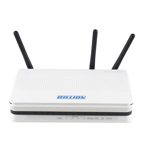
Page 13: Antenna Position Placement
2.5 Antenna Position Placement To get the best quality wireless reception out of your router, the antennas should be positioned like the following image to minimize the wireless interference caused between the antennas. -
Page 14: Cabling
Link and ADSL line LEDs are lit. If they are not, verify that you are using the proper cables. Ensure that all other devices connected to the same telephone line as your Billion router (e.g. telephones, fax machines, analogue modems) have a line filter connected between them and the wall socket (unless you are using a Central Splitter or Central Filter installed by a qualified and licensed electrician), and ensure that all line filters are correctly installed and the right way around. -
Page 15: Chapter 3
PC’s network components. The TCP/IP protocol stack and Ethernet network adapter must be installed. If not, please refer to your Windows-related or other operating system manuals. Any TCP/IP capable workstation can be used to communicate with or through the BiPAC 5200N. To configure other types of workstations, please consult the manufacturer’s documentation. -
Page 16: Configuring Pc In Windows 7
3.1.1 Configuring PC in windows 7 1. Go to Start. Click on Control Panel. Then click on Network and Internet. 2. When the Network and Sharing Center window pops up, select and click on Change adapter settings on the left window panel. - Page 17 4. Select Internet Protocol Version 4 (TCP/IPv4) then click Properties. 5. In the TCP/IPv4 properties window, select the Obtain an IP address automatically and Obtain DNS Server address automatically radio buttons. Then click OK to exit the setting. 6. Click OK again in the Local Area Connection Properties window to apply the new configuration.
-
Page 18: Configuring Pc In Windows Xp
3.1.2 Configuring PC in Windows XP 1. Go to Start / Control Panel (in Classic View). In the Control Panel, double-click on Network Connections 2. Double-click Local Area Connection. 3. In the Local Area Connection Status window, click Properties. 4. Select Internet Protocol (TCP/IP) and click Properties. -
Page 19: Configuring Pc In Windows 2000
3.1.3 Configuring PC in Windows 2000 1. Go to Start / Settings / Control Panel. In the Control Panel, double-click on Network and Dial-up Connections. 2. Double-click Local Area Connection. 3. In the Local Area Connection Status window click Properties. 4. -
Page 20: Configuring Pc In Windows 98/Me
3.1.4 Configuring PC in Windows 98/Me 1. Go to Start / Settings / Control Panel. In the Control Panel, double-click on Network and choose the Configuration tab. 2. Select TCP/IP ->NE2000 Compatible, or the name of your Network Interface Card (NIC) in your PC. 3. -
Page 21: Configuring Pc In Windows Nt4.0
3.1.5 Configuring PC in Windows NT4.0 1. Go to Start / Settings / Control Panel. In the Control Panel, double-click on Network and choose the Protocols tab. 2. Select TCP/IP Protocol and click Properties. 3. Select the Obtain an IP address from a DHCP server radio button and click OK. -
Page 22: Step-By-Step Installation
3.2 Step-by-Step Installation Insert the CD-ROM into CD-ROM drive Execute Windows Utility The Welcome screen will appear, click Next 4. The Hardware Installation screen will appear. Four links are shown on the screen. Click them one by one and follow the guidelines to complete hardware installation. - Page 23 4.3 ADSL Line connection 4.4 Filter connection 5. When finished Hardware Installation, click “Next” to proceed to next step, Network Card Selection. 6. Diagnostic screen. (If connection fails, the screen will show “FAIL” ,please check your router is connected correctly.) 7.
- Page 24 9. Please enter “Username” and “Password” as supplied by your ISP (Internet Service Provider) and click next. 10. Please configure the Wireless LAN setting and click next. (If your router does not support wireless, please ignore this screen and it will not appear.) 11.
- Page 25 13. The IE browser will be opened automatically when you finish installing.
-
Page 26: Factory Default Settings
3.3 Factory Default Settings Before configuring your router, you need to know the following default settings. Web Interface: Username: admin Password: admin LAN Device IP Settings: IP Address: 192.168.1.254 Subnet Mask: 255.255.255.0 ISP setting in WAN site: PPPoE DHCP server: DHCP server is enabled. -
Page 27: Lan And Wan Port Addresses
3.4 LAN and WAN Port Addresses The parameters of LAN and WAN ports are pre-set in the factory. The default values are shown below. LAN Port WAN Port IP address 192.168.1.254 The PPPoE function is enabled to Subnet Mask 255.255.255.0 automatically get the WAN port DHCP server function... -
Page 28: Configuring With Your Web Browser
Open your web browser, enter the IP address of your router, which by default is 192.168.1.254, and click “Go”, a user name and password window prompt will appear. The default username and password are “admin” and “admin”. Congratulation! You are now successfully logon to the BiPAC 5200N ADSL2+ Router! -
Page 29: Chapter 4
Advanced Setup (Firewall, Routing, NAT, QoS, ADSL) Access Management (ACL, Filter, SNMP, UPnP, DDNS) Maintenance (Administration, Time Zone, Firmware, SysRestart, Diagnositics) Status (Device Info, System Log, Statistics) Help Please see the relevant sections of this manual for detailed instructions on how to configure your Billion router. -
Page 30: Quick Start
4.1 Quick Start For detailed instructions on configuring WAN settings, see the Interface Setup section of this manual. The Quick Start Wizard is a useful and easy utility to help setup the device to quickly connect to your ISP (Internet Service Provider) with only a few steps required. It will guide you step by step to configure the password, time zone, and WAN settings of your device. - Page 31 Step1. Set your new password. Step2: Choose your time zone.
- Page 32 Step3: Set your Internet connection.
- Page 33 Step4: Wireless Network configuration.
- Page 34 Step5: Save settings of this ADSL Router.
-
Page 35: Interface Setup
4.2 Interface Setup Click this item to access the following sub-items that configure the ADSL2+ router: Internet, LAN and Wireless. These functions are described in the following sections. 4.2.1 Internet... - Page 36 ATM VC ATM settings are used to connect to your ISP. Your ISP provides VPI, VCI settings to you. In this Device, you can totally setup 8 VCs on different encapsulations, if you apply 8 different virtual circuits...
- Page 37 from your ISP. You need to activate the VC to take effect. For PVCs management, you can use ATM QoS to setup each PVC traffic line's priority. Virtual Circuit: VPI (Virtual Path Identifier) and VCI (Virtual Channel Identifier) define a virtual circuit.
- Page 38 Router will not accept the IP address if it is not in this format. PPPoA/PPPoE: Select this option if your ISP requires you to use a PPPoE connection. This option is typically used for DSL services. Select Dynamic PPPoE to obtain an IP address automatically for your PPPoE connection.
- Page 39 Multicast: IGMP (Internet Group Multicast Protocol) is a network-layer protocol used to establish membership in a Multicast group - it is not used to carry user data. The BiPAC 5200N supports both IGMP version 1 (IGMP-v1) and IGMP-v2. Select None to disable it MAC Spoofing: Select Enable and enter a MAC address that will temporarily change your router’s...
-
Page 40: Lan
Multicast: IGMP (Internet Group Multicast Protocol) is a network-layer protocol used to establish membership in a Multicast group - it is not used to carry user data. The BiPAC 5200N supports both IGMP version 1 (IGMP-v1) and IGMP-v2. Select None to disable it IGMP Snoop: Choose Disabled or Enabled IGMP Snoop function. - Page 41 If set to Disabled, the DHCP server will be disabled. If set to Relay, the BiPAC 5200N acts as a surrogate DHCP server and relays DHCP requests and responses between the remote server and the clients. Enter the IP address of the actual, remote DHCP server in the Remote DHCP Server field in this case.
-
Page 42: Wireless
4.2.3 Wireless This section introduces the wireless LAN and some basic configurations. Wireless LANs can be as simple as two computers with wireless LAN cards communicating in a peer-to-peer network or as complex as a number of computers with wireless LAN cards communicating through access points which bridge network traffic to the wired LAN. - Page 43 value between 20 and 1000. A beacon is a packet broadcast by the Router to synchronize the wireless network. RTS/CTS Threshold: The RTS (Request To Send) threshold (number of bytes) for enabling RTS/CTS handshake. Data with its frame size larger than this value will perform the RTS/CTS handshake.
- Page 44 Use WPS: select “yes” or “No” to enable or disable the WPS function SSID: The SSID is the unique name of a wireless access point (AP) to be distinguished from another. For security propose, change the default wlan-ap to a unique ID name to the AP which is already built-in to the router’s wireless interface.
- Page 45 WPS Settings WPS (WiFi Protected Setup) feature is a standard protocol created by Wi-Fi Alliance. This feature greatly simplifies the steps needed to create a Wi-Fi networks for a residential or an office setting. WPS supports 2 types of configuration methods which are commonly known among consumers: PIN Method &...
- Page 46 Wi-Fi Network Setup To enable WPS function as follows:...
- Page 47 PIN Method: Configure AP as Registrar 1. Jot down the client’s Pin (eg. 04640776). 2. Enter the Enrollee PIN code and then press Start WPS.
- Page 48 3. Launch the wireless client’s WPS utility (eg. Ralink Utility). Set the Config Mode as Enrollee, press the WPS button on the top bar, select the AP (eg. 5200N) from the WPS AP List column. Then press the PIN button located on the middle left of the page to run the scan.
- Page 49 4. The client’s SSID and security setting will now be configured to match the SSID and security setting of the registrar.
- Page 50 PIN Method: Configure AP as Enrollee 1. Jot down the WPS PIN (eg. 87343540).Press Start WPS.
- Page 51 2. Launch the wireless client’s WPS utility (eg. Ralink Utility). Set the Config Mode as Registrar. Enter the PIN number in the PIN Code column then choose the correct AP (eg. 5200N) from the WPS AP List section before pressing the PIN button to run the scan.
- Page 52 3. The router’s (AP’s) SSID and security setting will now be configured to match the SSID and security setting of the registrar. 4. Now to make sure that the setup is correctly done, cross check to see if the SSID and the security setting of the registrar setting match with the parameters found on both Wireless Configuration and Wireless Security Configuration page.
- Page 53 PBC Method: 1. Press the PBC radio button ,Then Start WPS. 2. Launch the wireless client’s WPS Utility (eg. Ralink Utility). Set the Config Mode as Enrollee. Then press the WPS button and choose the correct AP (eg. 5200N) from the WPS AP List section before pressing the PBC button to run the scan.
- Page 54 3. When the PBC button is pushed, a wireless communication will be established between your router and the PC. The client’s SSID and security setting will now be configured to match the SSID and security setting of the router.
- Page 55 Key 1 to Key 4: Enter the key to encrypt wireless data. To allow encrypted data transmission, the WEP Encryption Key values on all wireless stations must be the same as the router. There are four keys for your selection. The input format is in HEX style, 5 and 13 HEX codes are required for 64-bitWEP and 128-bitWEP respectively.
- Page 56 Pre-Shared key: The key for network authentication. The input format should be 8-63 ASKII characters or 64 hexadecimal characters Wireless MAC Address Filter The MAC filter screen allows you to configure the router to give exclusive access to up to 8 devices (Allow Association) or exclude up to 8 devices from accessing the router (Deny Association).
-
Page 57: Advanced Setup
4.3 Advanced Setup 4.3.1 Firewall Your router includes a firewall for controlling Internet access from your LAN and helping to prevent attacks from hackers. In addition to this, when using NAT (Network Address Translation) the router acts as a “natural” Internet firewall, since all PCs on your LAN use private IP addresses that cannot be directly accessed from the Internet. -
Page 58: Routing
4.3.2 Routing If you have another router with a LAN-to-LAN connection, you may create a static routing on the router that is the gateway to Internet. #: Item number Dest IP: IP address of the destination network Mask: The destination mask address. Gateway IP: IP address of the gateway or existing interface that this route uses. - Page 59 ADD Route Destination IP Address:This is the destination subnet IP address. IP Subnet Mask:A subnet mask allows IP networks to be subdivided for security and performance purposes. Gateway IP Address:This is the gateway IP address to which packets are to be forwarded.
-
Page 60: Nat
4.3.3 NAT The NAT (Network Address Translation - NAT, RFC 1631) is the translation of the IP address of a host in a packet. The default setting is Dynamic NAT. It provides dynamic Network Address Translation capability between LAN and multiple WAN connections, and the LAN traffic is routed to appropriate WAN connections based on the destination IP addresses and Route Table. - Page 61 The DMZ Host is a local computer exposed to the Internet. When setting a particular internal IP address as the DMZ Host, all incoming packets will be checked by the Firewall and NAT algorithms then passed to the DMZ host, when a packet received does not use a port number used by any other Virtual Server entries.
- Page 62 incoming connection attempts using specific ports to the PC on your network running the application. You will also need to use port forwarding if you want to host an online game server. The reason for this is that when using NAT, your publicly accessible IP address will be used by and point to your router, which then needs to deliver all traffic to the private IP addresses used by your PCs.
- Page 63 Rule Index: Choose the rule number. Application: Choose the predefined rule from Application drop-down menu or enter a custom name. Protocol: Choose the Protocol Type, ALL, TCP or UDP. Start Port Number: Enter a port number as the beginning number of the range which you want to give to devices to access in this field.
- Page 64 IP Address Mapping Address Mapping Rule: Shows the PVC where the rule will be applied to Rule Index: Choose the rule number. Rule Type: One-to-one: This is the mode maps one local IP address to one global IP address. Note that port numbers do not change for the One-to-one NAT mapping type. Many-to-One: This is the mode maps multiple local IP addresses to one global IP address.
-
Page 65: Qos
local IP addresses, then enter 0.0.0.0 as the Local Start IP address and 255.255.255.255 as the Local End IP address. This field is N/A for One-to-one and Server mapping types. Public Start IP: This is the start range for Inside Public IP Address. Enter 0.0.0.0 here if you have a dynamic IP address from your ISP. - Page 66 QoS can be toggled Activated and Deactivated. QoS must be activated before you can edit the following options. When you are done making changes, click on Add to save your changes.
- Page 67 Click on QoS Settings Summary to view the list of QoS rules that have been added.
- Page 68 Rule You can set 16 different QoS rules. Each QoS rule has its detail setting conditions like: 802.1p,application, DSCP, IP, MAC, Protocol, TOS, VLAN…etc, you can modify the default value to any new one you wish. Please notice that only when the packet fulfill every detail setting conditions here, then this packet will be remarked as the priority queue of each rule.
- Page 69 side. Source MAC: Set the Ethernet MAC value that you want to filter in source side. Source IP: Set the IP address value that you want to filter in source side. Source Mask: Set the subnet mask value that you want to filter in source side. Source Port Range: Set the port range value that you want to filter in source side.
-
Page 70: Adsl
4.3.5 ADSL ADSL Mode: The default setting is Auto Sync-Up. This mode will automatically detect your ADSL, ADSL2+, ADSL2, G.DMT, G.lite, and T1.413. But in some area, multimode cannot detect the ADSL line code well. If it is the case, please adjust the ADSL line code to G.DMT or T1.413 first. -
Page 71: Access Management
ACL Rule Index: This is item number Secure IP Address: The default 0.0.0.0 allows any client to use this service to remotely manage the BiPAC 5200N. Type an IP address to restrict access to a client with a matching IP address. -
Page 72: Filter
4.4.2 Filter You can Filter the packages by IP port , MAC and Application. Filter Type Filter Type Selection: There are three types ”IP/MAC Filter”, ”Application Filter”, and “URL Filter” that user can select for this connection. IP/MAC Filter Set Editing IP/MAC Filter Set Index: This is item number Interface: Select which channel (PVC) to configure. - Page 73 (“Incoming”).or Both. IP/MAC Filter Rule Editing IP/MAC Filter Rule Index: This is item number Rule Type: Choose “IP” or “MAC” rules Active: Select Yes from the drop down list box to enable IP filter rule. Source IP Address: The source IP address or range of packets to be monitored. Subnet Mask: It is the source IP addresses based on above source subnet IP Source Port Number: This Port or Port Ranges defines the port allowed to be used by the Remote/WAN to connect to the application.
- Page 74 Application Filter Application Filter: Select this option to Activated/Deactivated the Application filter. ICQ: Select this option to Allow/Deny ICQ. MSN: Select this option to Allow/Deny MSN. YMSG: Select this option to Allow/Deny Yahoo messenger. Real Audio/Video: Select this option to Allow/Deny Real Audio/Video.
- Page 75 URL Filter Active: Select Yes to enable URL Filter. URL Index: This is item number. URL: llow you to prevent users on your network from accessing particular websites by their URL.
-
Page 76: Snmp
Simple Network Management Protocol (SNMP) is a protocol used for exchanging management information between network devices. SNMP is a member of the TCP/IP protocol suite. BiPAC 5200N supports SNMP agent functionality which allows a manager station to manage and monitor the router through the network. -
Page 77: Upnp
Windows XP in order to support UPnP. Windows 2000 does not support UPnP. UPnP: Select this checkbox to activate UPnP. Be aware that anyone could use a UPnP application to open the web configurator's login screen without entering the BiPAC 5200N 's IP address... -
Page 78: Ddns
IP address of the router, which is assigned to you by your ISP. Dynamic DNS: Select this check box to use Dynamic DNS. Service Provider: www.dyndns.org My Host Name: Type the domain name assigned to your BiPAC 5200N by your Dynamic DNS provider. E-mail Address: Type your e-mail address. -
Page 79: Maintenance
4.5 Maintenance 4.5.1 Administrator In factory setting, the default password is admin, and that for user is also password. You can change the default password to ensure that someone cannot adjust your settings without your permission. Every time you change your password, please record the password and keep it at a safe place. -
Page 80: Time Zone
4.5.2 Time Zone The router does not have a real time clock on board; instead, it uses the Simple Network Time Protocol (SNTP) to get the current time from an SNTP server outside your network. Choose your local time zone. After a successful connection to the Internet, the router will retrieve the correct local time from the SNTP server you have specified. -
Page 81: Firmware
To upgrade the firmware of BiPAC 5200N, you should download or copy the firmware to your local environment first. Press the “Browse…” button to specify the path of the firmware file. -
Page 82: Sysrestart
screen. If the upload was not successful, the following screen will appear. Click Back to go back to the Firmware screen. DO NOT power down the router or interrupt the firmware upgrading while it is still in process. Improper operation could damage the router. Warning 4.5.4 SysRestart Click SysRestart with option Current Settings to reboot your router (and restore your last... -
Page 83: Diagnostics
4.5.5 Diagnostics The Diagnostic Test page shows the test results for the connectivity of the physical layer and protocol layer for both LAN and WAN sides... -
Page 84: Status
4.6 Status 4.6.1 Device Info This page displays the current information for the ADSL Router. It will display the Firmware version, LAN, WAN, and MAC address information. Device Information Firmware Version: This is the Firmware version MAC Address: This is the MAC Address... - Page 85 IP Address: LAN port IP address. Sub Net Mask: LAN port IP subnet mask. DHCP Server: LAN port DHCP role - Enabled, Relay or disabled Status: “Not connected” or “Connected” Virtual Circuit: There are eight groups of PVC can be defined. VPI: The valid range for the VPI is 0 to 255 VCI: The valid range for the VCI is 1 to 65535 Connection Type: Name of the WAN connection.
-
Page 86: System Log
4.6.2 System Log Display system logs accumulated up to the present time. You can trace historical information with this function. -
Page 87: Statistics
4.6.3 Statistics Read-only information here includes port status and packet specific statistics. Also provided are "Transmit Statistics" and "Receive Statistics". Ethernet Interface: This field displays the type of port Transmit Frames: This field displays the number of frames transmitted in the last second. - Page 88 ADSL Transmit total PDUs: This field displays the number of total PDU transmitted in the last second. Transmit total Error Counts: This field displays the number of total error transmitted in the last second. Receive total PDUs: This field displays the number of total PDU received in the last second.
- Page 89 Tx Errors Count: This field displays the number of errors frames transmitted in the last second. Tx Drops Count: This field displays the number of drops frames transmitted in the last second. Rx Frames Count: This field displays the number of frames received in the last second.
-
Page 90: Help
4.7 Help This help page provides you some useful messages such as the introductions of some concepts and some guidances. When some problems are encountered, you can turn to this page for help. - Page 91 For example, if you don’t understand what is Quick Start, you can go to this page, click on Quick Start, then you’ll see some messages about it, and understand it quickly. This function provides you an easy way to help yourself.
-
Page 92: Chapter 5
Chapter 5 Troubleshooting If the ADSL2+ Router is not functioning properly, you can refer first to this chapter for simple troubleshooting before contacting your service provider. This could save your time and effort but if the symptoms persist, then consult your service provider. Problems starting up the router Problem Corrective Action... -
Page 93: Problems With The Wan Interface
Problems with the WAN Interface Problem Corrective Action Initialization of the Ensure that the telephone cable is connected properly from PVC connection the ADSL port to the wall jack. The ADSL LED on the front (“linesync”) failed. panel of the router should be on. Check that your VPI, VCI, encapsulation type and type of multiplexing settings are the same as those provided by your ISP. -
Page 94: Appendix
Most problems can be solved by referring to the Troubleshooting section in the User’s Manual. If you cannot resolve the problem with the Troubleshooting chapter, please contact the dealer where you purchased this product. Contact Billion WORLDWIDE http://www.billion.com MAC OS is a registered Trademark of Apple Computer, Inc.
Need help?
Do you have a question about the BiPAC 5200N and is the answer not in the manual?
Questions and answers