Table of Contents
Advertisement
Quick Links
Instructions - Parts
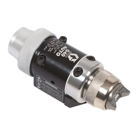
Automatic G40 Air-Assisted
Spray Guns
For air-assisted spraying of paints and coatings. For professional use only.
Approved for use in explosive atmospheres.
4000 psi (28 MPa, 280 bar) Maximum Working Fluid Pressure
100 psi (0.7 MPa, 7 bar) Maximum Working Air Pressure
See page 3 for model information.
Important Safety Instructions
Read all warnings and instructions in this manual.
Save these instructions.
Part No. 288046 Spray Gun shown
mounted on Part No. 288217 Manifold
311052E
ENG
TI8087b
II 2 G c T6
Advertisement
Table of Contents
Troubleshooting

Subscribe to Our Youtube Channel
Related Manuals for Graco 288046


Summary of Contents for Graco 288046
- Page 1 100 psi (0.7 MPa, 7 bar) Maximum Working Air Pressure See page 3 for model information. Important Safety Instructions Read all warnings and instructions in this manual. Save these instructions. Part No. 288046 Spray Gun shown mounted on Part No. 288217 Manifold 311052E TI8087b II 2 G c T6...
-
Page 2: Table Of Contents
Related Manuals Contents Related Manuals ......2 Models ........3 Warnings . -
Page 3: Models
Models A manifold is required for each gun to be installed. Refer to the Parts section for manifold information. G40 Standard Spray Gun, 288046, Series A • High pressure spray gun with Carbide ball and Car- bide seat. • Includes AAP series tip of choice. -
Page 4: Warnings
Warnings Warnings The following warnings are for the setup, use, grounding, maintenance, and repair of this equipment. The exclama- tion point symbol alerts you to a general warning and the hazard symbol refers to procedure-specific risk. Refer back to these warnings. Additional, product-specific warnings may be found throughout the body of this manual where applicable. - Page 5 PRESSURIZED EQUIPMENT HAZARD Fluid from the gun/dispense valve, leaks, or ruptured components can splash in the eyes or on skin and cause serious injury. • Follow Pressure Relief Procedure in this manual, when you stop spraying and before cleaning, checking, or servicing equipment. •...
-
Page 6: Installation
Installation Installation Ventilate Spray Booth Check and follow all National, State, and Local codes regarding air exhaust velocity requirements. Check and follow all local safety and fire codes. Configure Gun and Manifold The gun is supplied with an internal fluid plug and seals (5, 6, 7). -
Page 7: Install Air Fittings
Install Air Fittings 1. Install the supplied 1/4 in. tube fitting into the cylin- der (CYL) air port. 2. Install 3/8 in. tube fittings into the atomization (ATOM) air port and the fan (FAN) air port. . 2: Air Fittings Ground System The following grounding instructions are minimum requirements for a system. -
Page 8: Mount Gun
Installation Mount Gun Reciprocating Arm Rod Mount To mount the gun on a reciprocating arm rod [0.5 in. (13 mm) diameter maximum]: 1. Insert the mounting bar (A) through the hole in the manifold as shown in F . 3. Use the 1/8 in. -
Page 9: Connect Air Line
Connect Air Line 1. Install an air/water separator and an air line filter to ensure a clean, dry air supply to the gun. Dirt and moisture in the line can ruin the appearance of your finished piece. 2. Install an air pressure regulator on each gun air sup- ply line. -
Page 10: Connect Fluid Line
Installation Connect Fluid Line Before connecting the fluid line, blow it out with air and flush it with solvent. Use solvent that is compat- ible with the fluid to be sprayed. A fluid drain valve(s) is required in your system to assist in relieving fluid pressure in the displacement pump, hose and gun;... -
Page 11: Setup
Setup Flush Spray Gun Before running any paint through the spray gun: 1. Flush the gun with a solvent that is compatible with the fluid to be sprayed, using the lowest possible fluid pressure and grounded metal container. 2. Perform Pressure Relief Procedure; see page 12. Select a Spray Tip and Air Cap The fluid flow and pattern width depend on the size of the spray tip, the fluid viscosity, and the fluid pressure. -
Page 12: Operation
Operation Operation Pressure Relief Procedure 1. Turn off the air and fluid supply to the gun. 2. Close the bleed-type master air valve (required in the system). 3. Trigger the gun into a grounded metal waste con- tainer to relieve the fluid pressure. . -
Page 13: Apply Fluid
too little air no air . 11: Correct Spray Pattern Apply Fluid The spray gun has a built-in lead and lag operation. When triggered, the gun begins emitting air before the fluid is discharged. When the trigger actuation air is stopped, the fluid stops before the air flow stops. -
Page 14: Maintenance
Maintenance Maintenance Daily Gun Care Solvent left in gun air passages could result in a poor quality paint finish. Do not use any cleaning method which may allow solvent into the gun air passages. Do not point the gun up while cleaning it. TI8100a Do not immerse the gun in solvent. -
Page 15: General System Maintenance
General System Maintenance 1. Perform Pressure Relief Procedure, page 12. 2. Clean the fluid and air line filters daily. 3. Check for any fluid leakage from the gun and fluid hoses. Tighten fittings or replace equipment as needed. 4. Flush the gun before changing colors and whenever you are done operating the gun. - Page 16 Maintenance 7. Turn off the solvent supply. 8. Perform Pressure Relief Procedure, page 12. 9. Disconnect the solvent supply hose from the gun. 10. Dip the end of a soft-bristle brush into a compatible solvent. Do not continuously soak the brush's bris- tles with solvent and do not use a wire brush.
-
Page 17: Troubleshooting
Troubleshooting Check all possible remedies in the troubleshooting charts before disassembling the gun. Some improper patterns are caused by the improper balance between air and fluid. Refer to Spray Pattern Troubleshooting, page 19. General Troubleshooting Problem Fluid leakage through venting holes. Air leakage through venting hole. - Page 18 Troubleshooting Problem Fluid needle will not trigger. Fluid does not shut off. Cause Loose or missing fluid needle stop (21) or setscrew (19). Broken fluid needle (14). Air leaking around piston (20). Swollen piston o-ring (22). Insufficient air pressure on trigger. Spray tip (9) is plugged.
-
Page 19: Spray Pattern Troubleshooting
Spray Pattern Troubleshooting Problem Fluttering spray. Spitting spray. Irregular pattern. Pattern pushed to one side, same side of air cap gets dirty. 311052E Cause Insufficient fluid supply. Air in paint supply line. Worn diffuser-seat (10) or needle (14) ball. Dirty spray tip (9) or air cap (30). Fluid build-up or spray tip partially plugged. -
Page 20: Service
Service Service Follow the Service Notes in F when reassembling the gun. Gun repair kits are available. See page 34. Refer- ence numbers marked with an asterisk (*) in the service procedures are included with the 288171 Air Seal Repair Kit. Reference numbers marked with a symbol (†) in the service procedures are included with the 288136 Fluid Repair Kit. - Page 21 10. If gasket (15) needs to be replaced, unscrew the two screws (18) and separate the fluid housing (2) and piston housing (1). Inspect gasket (16) and replace if needed. Gasket (16) is attached to assembly with adhesive; therefore, if you are replacing gasket (16), ensure that a replacement gasket is available.
- Page 22 Service Cutaway View: Part No. 288044 Gun Shown . 17 4† SERVICE NOTES: Lubricate threads with anti-seize lubricant Lubricate with light-weight oil Do not lubricate Torque to 155-165 in-lb (18-19 N•m) Apply semi-permanent anaerobic sealant Torque to 4-5 in-lb (0.45-0.56 N•m) Tighten cap (27) until it bottoms out TI8123a 311052E...
-
Page 23: Diffuser Seat Replacement
Diffuser Seat Replacement • See Accessories, page 34. • Clean parts with a solvent that is compatible with the parts and the fluid being sprayed. 1. Perform Pressure Relief Procedure, page 12. 2. Remove gun from manifold. 3. Remove the air cap retaining ring (8), air cap (30), and spray tip (9). -
Page 24: Parts
Parts Parts † AA RAC Assembly included with Model 288053 only . 18 ✓ ✓✿ ✓ † †✿ †✿ TI8228a 14 (ref) SERVICE NOTES: Lubricate threads with anti-seize lubricant Lubricate with light-weight oil Do not lubricate Torque to 65 in-lb (7.3 N•m) Apply semi-permanent anaerobic sealant Torque to 4-5 in-lb (0.45-0.56 N•m) Tighten cap (27) until it bottoms out... - Page 25 15H702 INSERT, plastic 46★ 249478 GUARD, RAC, G40 ◆ Model 288044 only. ❖ Model 288046 only. ★ Model 288053 only. † Included in Fluid Seal Repair Kit 288136. Included in Air Seal Repair Kit 288171. ✓ Included in Seat Repair Kits 249424 (plastic) or 249456 (carbide).
- Page 26 Parts Part No. 288217 North America Manifold with side fluid ports Part No. 288218 International Manifold with side fluid ports Ref. Part No. Description MANIFOLD, side fluid ports 120388❖ FITTING, tube, air inlet; 1/4 in. OD tube x 1/8 npt(m) 120538◆...
- Page 27 Part No. 288221 Manifold with bottom fluid ports Ref. Part No. Description MANIFOLD, bottom fluid ports 120388 FITTING, tube, air inlet; 1/4 in. OD tube x 1/8 npt(m) 114246 SCREW, set; 5/16;0.437 in. long 166846 NIPPLE, SST; 1/4 npsm, straight pipe thread x 1/4 npt 120389 FITTING, tube, air line;...
- Page 28 Parts Part No. 288224 High Pressure Air-Assisted Manifold with side fluid ports and fan adjustment valve Part No. 24C343 International Manifold with side fluid ports Ref. Part No. Description ---- MANIFOLD, fan adjustable 244029 VALVE, fan, assy. FITTING, tube, air inlet 120388❖...
- Page 29 Part No. 288160 Rear Port Manifold, North America Part No. 288211 Rear Port Manifold, International Ref. Part No. Description MANIFOLD, aluminum FITTING, fluid path 15H521❖ 1/4 npsm 15J003◆ #5 JIC 116475 SCREW, SHCS, M4 x 12 120353 O-RING, PTFE 15J077 O-RING, PTFE 114246 SCREW, set, hex soc...
-
Page 30: Notes
Notes Notes 311052E... -
Page 31: Aap Series Tip And Air Cap Selection Charts
AAP Series Tip and Air Cap Selection Charts AAP Series Precision Spray Tips Order desired tip (Part No. AAPxxx) where xxx is the size code for the chart. Tips are physically marked with Xxxx, where xxx is the size code from the chart. * Fluid Output, fl oz/min (lpm) Orifice Size in. -
Page 32: Ltx Series Rac Tip Selection Charts
LTX Series RAC Tip Selection Charts LTX Series RAC Tip Selection Charts For use with G40 RAC Housing * Fluid Output, fl oz/min (lpm) at 2000 psi Orifice Size in. (mm) (14.0 MPa, 140 bar) 0.009 (0.229) 11.2 (0.33) 0.011 (0.279) 16.6 (0.49) 0.013 (0.330) 23.3 (0.69) -
Page 33: Rac Switch Tips
RAC Switch Tips FFT Fine Finish RAC Spray Tips Order desired tip (Part No. FFTxxx) where xxx is the size code for the chart. * Fluid Output, fl oz/min (lpm) Orifice Size in. at 2000 psi (mm) (14.0 MPa, 140 bar) 0.008 (0.203) 8.8 (0.26) 0.010 (0.254) -
Page 34: Accessories
Accessories Accessories Gun Manifolds Order separately; not included with gun (See Parts, page 25) Part No. 288217 North America Manifold with side fluid ports Part No. 288218 International Manifold with side fluid ports Part No. 288221 Manifold with bottom fluid ports Part No. - Page 35 Air Cap Seal Kit 253032 Pack of five seals and five o-rings for the air cap assembly. Plastic Seat Repair Kit 249424 Kit includes replacement plastic seat (pack of ten), and seat nut. SST Seat Repair Kit 287962 Kit includes assembled diffuser with SST seat (15H282) for use with pigmented acid catalyzed materials.
-
Page 36: Dimensions
Dimensions Dimensions 2.0 in. (50.8 mm) TI8113a 3.86 in. (98.0 m) 4.9 in. (124.5 mm) 3.0 in. 1.375 in. (76.2 mm) (34.9 mm) 2.0 in. (50.8 mm) 2.40 in. (60.96 mm) TI8127a . 24 311052E... -
Page 37: Mounting Hole Layout
Mounting Hole Layout 0.805 in. (20.5 mm) 0.187 in. (4.8 mm) Remove set screws when using bottom mounting pattern. . 25: 311052E 0.5 in. (12.7 mm) 0.4 in. (10.2 mm) 1.375 in. (35 mm) Two 0.128 diameter x 2.125 in. 0.31 in. -
Page 38: Mounting Hole Layout
Mounting Hole Layout Mounting Hole Layout Rear Port Manifold Gun with Rear Port Manifold 3.200 in. (81.28 mm) Retrofit Adapter Plate 2.007 in. (50.98 mm) 1.375 in. (34.93 mm) . 26: Mounting Hole Layouts 0.205 in. (5.21 mm) 0.875 in. (22.23 mm) 3.720 in. -
Page 39: Technical Data
Technical Data Maximum Working Fluid Pressure ....4000 psi (28 MPa, 280 bar) Maximum Working Air Pressure ....100 psi (0.7 MPa, 7 bar) Maximum Working Fluid Temperature . -
Page 40: Graco Standard Warranty
Graco Standard Warranty Graco warrants all equipment referenced in this document which is manufactured by Graco and bearing its name to be free from defects in material and workmanship on the date of sale to the original purchaser for use. With the exception of any special, extended, or limited warranty published by Graco, Graco will, for a period of twelve months from the date of sale, repair or replace any part of the equipment determined by Graco to be defective.
Need help?
Do you have a question about the 288046 and is the answer not in the manual?
Questions and answers