
Related Manuals for Lowrance Elite 5 Sonar/GPS


Summary of Contents for Lowrance Elite 5 Sonar/GPS
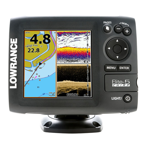
- Page 1 Elite 5 Sonar/GPS & Elite 5m GPS Installation & Operation Installation & Operation manual manual...
- Page 2 Copyright © 2009 Navico All rights reserved. Lowrance® and Navico® are registered trademarks of Navico. Fishing Hot Spots® is a registered trademark of Fishing Hot Spots Inc. Navionics® is a registered trademark of Navionics, Inc. Points of Interest Data in this unit are by infoUSA, copyright© 2001-2008, All Rights Reserved.
-
Page 3: Table Of Contents
Table of Contents Installation ..........2 Chart Operation ........25 Basic Operation ........12 Waypoints, Routes, Trails ......26 Creating a route ..........27 Menu operation..........13 Navigating a route ........29 Fishing Mode (Elite 5 only) ......15 To cancel navigation: ........30 Advanced Mode.......... -
Page 4: Installation
Installation Elite Series Installation This document covers the installation of the transducer and display unit installation, which includes connecting the unit to power and installing the unit on the bracket mount. Make sure you read all the installation instructions before drilling holes in your vessel. - Page 5 Installation A. Select a transducer location Good locations To function properly the Skimmer transducer must be in the water at all times and in a location that has a smooth flow of water when the boat is moving. If the transducer is not placed in a smooth flow of water, interference caused by bubbles and turbulence may show on-screen as random lines or dots.
- Page 6 Installation Slide the transducer into the bracket and temporarily slide the bolt through the transducer bracket. Hold the transducer assembly against the transom. Look at the transducer from the side. If it is parallel to the ground, then the “A” position is correct. If the transducer can not be adjusted so its face is parallel to the ground, remove the transducer and ratchets from the bracket.
- Page 7 Installation D. Attaching the Transducer to the Transom Transom Adjust the transducer so its face is parallel with the ground and its center line is even with the bottom of the boat hull. Hold the transducer and bracket assembly against the transom.
- Page 8 Installation Shoot-thru-hull Skimmer and Pod transducer installation Before attempting any installation on boats with flotation material sandwiched within the hull, consult the boat manufacturer. In a shoot-thru-hull installation the transducer is epoxied to the inside of the boat hull. A transducer can not shoot through wood or metal hulls. Wood and metal hulls require either a transom mount or thru-hull installation.
- Page 9 Installation To use shoot-thru-hull installation: Sand the inside surface of the hull, where the transducer is to be epoxied, and the face of the transducer. Sand the hull until it is smooth to the touch. The sanded area should be about 1-1/2 times the diameter of the transducer.
- Page 10 Installation Trolling motor Skimmer and Pod Installation The TMB-S trolling motor bracket (Part No. 51-45) is an optional accessory and is available through LEI Extras at www.lei-extras.com. The TMB-S bracket is used to attach a one-piece bracket skimmer transducer to a trolling motor. The Pod transducer does not need a TMB-S trolling motor bracket to be installed on a trolling motor.
- Page 11 Installation Tighten the adjustable strap Adjustable strap securely to the trolling motor. Plastic ties (not Make sure there is enough slack included) in the transducer cable for the trolling motor to turn freely. Transducer cable Mounting display unit Before mounting the display unit mount, make sure there is nothing in the area that will obstruct the display unit when it is installed on the bracket.
-
Page 12: To Install Bracket Mount
Installation To install bracket mount: Place the bracket on the desired mounting surface and mark the four mounting holes. If you want to run the unit’s cables up through the mounting surface, make a mark in the center of the bracket mounting surface. Drill pilot holes for the four mounting holes. - Page 13 Installation External GPS port Power port Speed/temp port; Red (power) also used for NMEA wire 0183 Optional temp 3 Amp sensor fuse Black (ground) wire Optional paddlewheel speed/temp sensor...
-
Page 14: Basic Operation
Basic Operation PAGES: Opens ZOOM Keys: used to zoom in/zoom Getting Started pages menu; out; press and hold both keys to To turn on/off the unit, allows you to create Man Overboard waypoint select a page to press and hold the LIGhT/ Turn unit on/off view POwER... -
Page 15: Menu Operation
Basic Operation Menu operation This unit has four page screens: Steer, Sonar, Chart/ Sonar and Chart. Sonar Page Sonar menu (Elite 5 only) Chart or sonar menu will appear Pages menu depending on which panel is Page context menus active. Press The Sonar, Chart/Sonar and Chart pages have menus PAGES Chart/Sonar page... -
Page 16: Accessing Menu Items
Basic Operation Making adjustments There are several menu types used to make adjustments to options and settings, including scrollbars, on/off features and dropdown menus. Scrollbars Settings menu Select the scrollbar and press Accessing menu items the keypad left (decrease) or right (increase). -
Page 17: Fishing Mode (Elite 5 Only)
Basic Operation Entering text Exiting menus Some functions, like naming a waypoint, route or If a screen or menu has an exit option (Close, Return trail, will require you to input text. to screen, Exit dialog) highlight the exit option and press EnTER to exit. -
Page 18: Advanced Mode
Basic Operation Advanced Mode Fishing Mode Options Enables advanced features General Bottom brown/blue background; 50% ping speed and settings. Shallow Bottom brown/white background; best for depths Water less than 100 feet Advanced Mode features Fresh Bottom brown/white background; 50% ping Colorline Enables manual control of colorline Water... -
Page 19: Steer Page
Pages Surface Clutter Colorline Direction to Compass Overlay Data Fish arches Current Track waypoint Cursor Range Scale Location and depth Navigation Depth Your location information Frequency Amplitude Scope Sonar Page Steer Page Displays the water column moving from right to left The Steer page has a compass that shows your current on your unit’s screen. -
Page 20: Chart Page
Pages Current location Depth contours Waypoint Chart/Sonar Page Zoom Current location; Range distance to destination Chart/Sonar page (Elite 5 only) Chart Page Consists of map that moves in real-time as you move. Consists of a chart/sonar splitscreen. Press the By default, the map is shown from a birds-eye view PAGES key twice to switch active panels. -
Page 21: Overlay Data
Pages Overlay Data Show Displays selected data on the Sonar, Chart/Sonar and Shows/hides selected overlay data on the display. Chart pages. To select overlay data: From a sonar or chart page, press MEnU. Overlay data and press EnTER. Select Select Configure and press EnTER. -
Page 22: Sonar Operation: Elite 5
Sonar Operation: Elite 5 Using your Sonar Blue sonar history bar Cursor This section covers sonar operation, which includes viewing sonar history and using sonar menus, con- text menus and submenus. Information is arranged in the same order as the menus. Move the blue sonar history bar all the way to the right to resume normal sonar scrolling. -
Page 23: Sensitivity
Sonar Operation: Elite 5 Adjust Waypoint name (Advanced Mode) keyboard Waypoint icon New Waypoint menu Depth Range Lat/Lon window Frequency (Advanced Mode) New waypoint menu Sonar Options Sonar Menu (Elite 5 only) Adjust (Advanced Mode only) Used to make adjustments to Settings Sensitivity and Colorline. -
Page 24: Depth Range
Sonar Operation: Elite 5 Auto Sensitivity Keeps sensitivity at a level that works will under most conditions, reducing the needs for adjustments. Auto Sensitivity is turned on by default. NOTE: You can make minor changes to Sensitivity set Sensitivity set sensitivity with Auto Sensitivity turned to 65 percent. -
Page 25: Frequency
Sonar Operation: Elite 5 Ping Speed (Advanced Mode only) Controls the rate the transducer uses to send sonar waves into the water. Custom range menu Sonar Options menu Accesses sonar display settings Frequency and configuration options. Controls the transducer frequency used by the unit. This unit supports two frequencies: 200kHz and 83kHz. -
Page 26: Sonar Operation
Sonar Operation Color Ice Mode Allow you to change the look of the display Turns on a package of sonar settings that enhance using palettes with varying degrees of color and the performance of your unit when ice fishing. brightness. Stop Sonar Pauses the sonar chart, allowing you to get a closer look at sonar echoes. -
Page 27: Chart Operation
Chart Operation Using your Chart This section covers chart operation, which includes New waypoint saving, loading and navigating, waypoints, routes and trails and using chart menus, context menus and Waypoints, submenus. Routes & Settings menu Trails (Advanced mode) Orientation Overlay data Chart menu New Waypoint Creates a waypoint at your current location or at the... -
Page 28: Waypoints, Routes, Trails
Chart Operation waypoints, Routes, Trails Edit Show Used to create, edit, navigate and delete waypoints, Delete routes and trails. Press the keypad left/right to toggle between waypoint, routes and trails tabs. Sort Delete all Waypoints menu Waypoints Screen Waypoints menu Load from card Save to card Edit... -
Page 29: Creating A Route
Chart Operation Sort Controls how the waypoints list will be Creates a new waypoint at sorted — by name or by nearest. the cursor or vessel position. You can also select waypoint name, icon and latitude/ Routes Screen longitude from the new waypoint menu. - Page 30 Chart Operation Select Add to end and press EnTER. Shows selected route waypoint on the chart Highlight Waypoint from list and press EnTER. Inserts waypoint between existing route waypoints Select the desired waypoint and press EnTER. Press MEnU and select Add to end to add another waypoint to the route.
-
Page 31: Navigating A Route
Chart Operation Creating a route using points from chart: New Route screen Edit Route screen Repeat Steps 1-4 from the instructions for Creating a route from waypoint list. Points from chart and press Select EnTER. The chart screen will appear. Move the cursor to the desired location. -
Page 32: To Cancel Navigation
Chart Operation To access the Edit or New Route menu, select Edit or To cancel navigation: New on the Routes menu and press EnTER. Press Menu from the chart screen. To finalize changes on the Edit or New Route menus, Navigation Select highlight the Accept button and press EnTER. -
Page 33: Creating Trails
Chart Operation Trails Screen New Trail menu Edit Trail menu Used to create, edit, navigate and delete trails. Use the keypad to highlight the Trails tab to access the Trails screen. Delete Delete All Trails menu Load from card Save to card Routes screen Routes menu To create a trail:... -
Page 34: Navigating A Trail
Chart Operation Edit and New Trail menus To save a trail as a route: Allows you to edit/create trails, select trails names, Highlight the desired trail on the Trails trail color, trail display and the trail being recorded. screen and press EnTER. The Edit You can also convert a trail into a route from the Edit Trail menu will appear. - Page 35 Chart Operation Create route (from trail) Overlay Data and Settings Overlay Data is covered in the Basic Operation Used to convert a trail into section. Settings accesses the Settings menu, but a route, which allows you to will only be shown on the map when the unit is in navigate a selected trail.
-
Page 36: Settings Menu
Settings Settings Menu System Accesses to installation and configuration settings Adjusts unit settings like language, mute audio and for your unit. advanced mode. System Settings Navigation Settings Language menu Time menu GPS Source menu Chart Settings GPS status Sonar Settings screen Tmp/Spd port System menu... -
Page 37: Tmp/Spd Port
Settings Set Language GPS Source Selects the type of GPS an- Selects the language used on menus tenna used by your unit. and text boxes. Tmp/Spd port Mute Audio Selects the type of device Turns on/off unit audio. Refer to the Basic Operation connected to the unit’s Temp/ section for instructions. -
Page 38: Navigation
Settings navigation Off Course Distance Sets Off Course Distance threshold for the Off Controls Arrival Radius and Off Course distance Course alarm. When the selected off course distance settings and is used to turn on/off WAAS/MSAS/ is exceeded, the Off Course alarm will sound when EGNOS. -
Page 39: Grid Lines
Chart Data view of the map, if the screen becomes cluttered with Selects map data that will be used waypoints, routes and/or trails. on the Chart display (Lowrance or Navionics regional map). waypoints, Routes, Trails COG Extension Accesses the Waypoints, Routes & Trails screen. -
Page 40: Sonar
Settings Sonar Surface Clarity (Advanced Mode only) Used to make adjustments to Sonar options and dis- play settings like Noise Rejection, Surface and Fish- Surface Clarity reduces ing Mode. surface clutter by decreasing the sensitivity of the receiver Surface clarity Noise rejection menu menu... -
Page 41: Installation Menu
Settings Reset Fishing Mode Switches Fishing Mode to the default General Use setting. Transducer Keel Keel Offset (-3.5 feet) Before setting keel offset, measure the distance from Installation menu the transducer to the lowest part of the keel. If, for example, the keel is 3.5 feet below the transducer, it Installation will be input as –3.5 feet. -
Page 42: Alarms
Settings Alarms Units Enables alarms and selects alarm thresholds. Arrival, Allows you to select the unit of measure for Distance, Off Course and Anchor alarms are only available in Speed, Depth and Temperature, when the unit is in Advanced mode. Advanced mode. -
Page 43: Index
Index Sonar Options menu 23 Sonar Page 17 Advanced Mode 16 Fish ID 24 Navigating a route 29 Sonar settings 38 Alarms 40 Fishing Mode 15 Navigating a trail 32 Steer Page 17 Amplitude Scope 24 Frequency 23 Navigation menu 36 Surface Clarity 38 Auto Sensitivity 22 Noise Rejection 38... -
Page 44: Specifications
Sonar (Elite 5 only) Lowrance, Eagle & Northstar Explorer, excluding Lowrance HDS: Twelve (12) months 1000ft (305m) Peripheral devices for all Navico brands including, but not limited to, transducers, fuel and... - Page 45 Navico will, at its sole discretion, repair or replace with new or refurbished parts or product, • consumable items, whether repaired or replaced including, but not limited to the following: or equivalent product, any proven defective products or components returned to Navico, or fuses, batteries, bulbs, bearings, motor brushes, drive-belts, magnetrons, paddlewheels, pad- its approved agent during the Warranty Period in accordance with the terms, conditions and dlewheel bearings, paddlewheel blades and paddlewheel shafts;...
- Page 46 liable for loss of revenue or profits, failure to realize savings or other benefits, or any other This License Agreement will terminate immediately without prior notice from us if you fail to comply with or violate any of the provisions of this Agreement. Upon termina- special, incidental or consequential damages caused by the use, misuse or inability to use tion, you will promptly return all products containing one or more Databases to us.
-
Page 51: Accessory Ordering Information
LEI Extras, Inc. is the accessory source for sonar and GPS products manufactured by Lowrance Electronics. To order Lowrance accessories, please contact: 1) Your local marine dealer or consumer electronics store. To locate a Lowrance dealer, visit the web site, www.lowrance.com, and look for the Dealer Locator; or, consult your telephone directory for listings. - Page 52 Visit our website: www.lowrance.com © Copyright 2009 *988-0180-01a* All Rights Reserved Navico Holding AS...
Need help?
Do you have a question about the Elite 5 Sonar/GPS and is the answer not in the manual?
Questions and answers