
Related Manuals for GMC LSM210A


Summary of Contents for GMC LSM210A
- Page 1 SLIDE COMPOUND MITRE SAW WITH LSMS210A LSMS250A INSTRUCTION MANUAL Black Magenta Cyan Yellow Code: LSMS210A & LSMS250A Date:060926 Edition: 03 Op: AB...
-
Page 2: Table Of Contents
Contents Warranty Introduction Environmental protection Description of symbols Specifications Safety rules for laser lights General safety instructions Additional safety rules for mitre saws Accessories Know your product Unpacking Transportation Bench mounting Release knob Slide lock Mitre table lock Bevel lock Clamp assembly Spindle lock button Rotating lower blade guard... -
Page 3: Introduction
Introduction Your new GMC power tool will more than satisfy your expectations. It has been manufactured under stringent GMC Quality Standards to meet superior performance criteria. You will find your new tool easy and safe to operate, and, with proper care, it will give you many years of dependable service. -
Page 4: Safety Rules For Laser Lights
Always remove the plug from the mains socket before making any adjustments or maintenance, including changing the blade. To ensure safe operation of the mitre saw you must follow these guidelines – • Select the correct blade for the material to be cut. - Page 5 • Do not use the saw to cut materials other than those recommended by the manufacturer. • The mitre saw can be safely carried by the main handle but only once it has been removed from the mains power and secured in the locked down position.
-
Page 6: Additional Safety Rules For Mitre Saws
• Ensure that there is adequate general or localised lighting. • Do not use the saw unless the guards are in place. • Do not use the saw to cut metal or masonry. • Do not let anyone under 18 years operate this saw. - Page 7 Always hold the saw on parts that are insulated. If you accidentally cut into hidden wiring or the saw’s own cable, the metal parts of the saw will become “live”. Switch off at the mains and remove the plug immediately.
-
Page 8: Accessories
Accessories The GMC LSMS210A and LSMS250A slide compound mitre saws are supplied with the following accessories as standard: • Saw blade (fitted) • Workpiece clamp • 6mm Hex key • Side bars x2 • Dust bag • Instruction manual... -
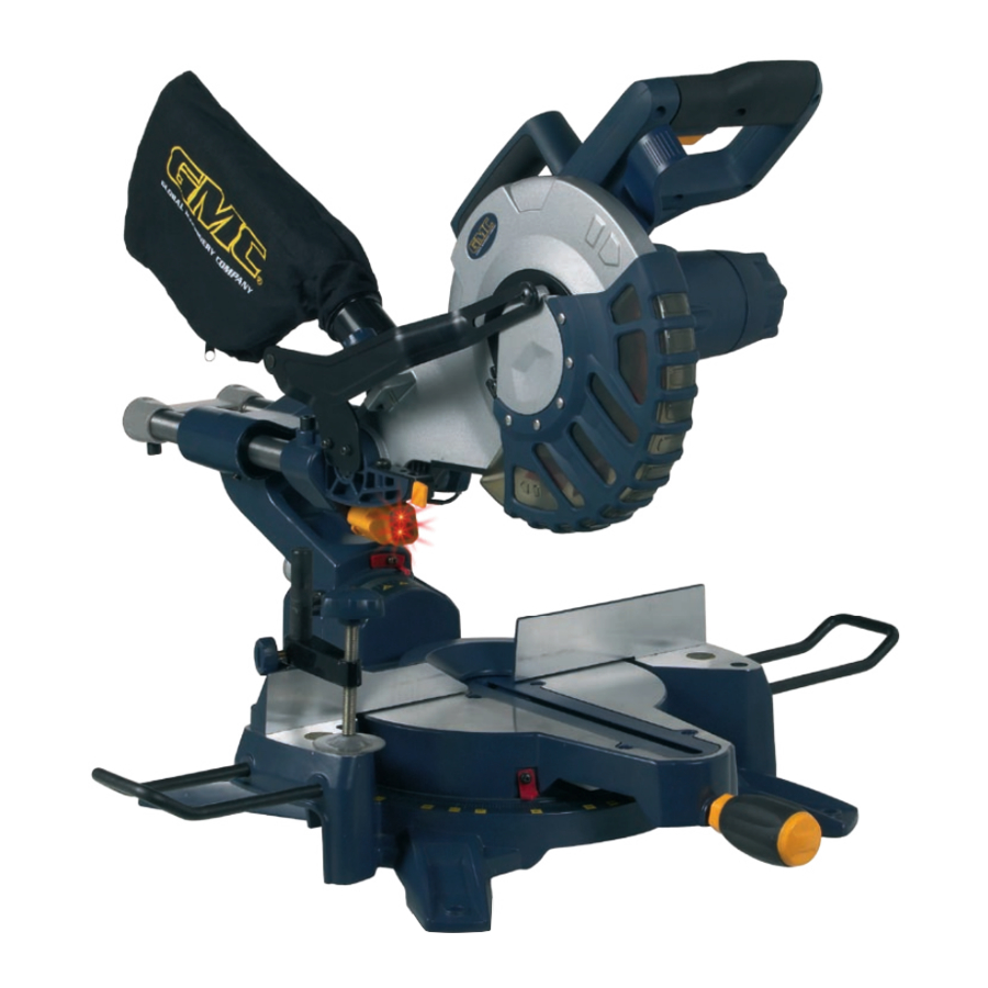
Page 9: Know Your Product
Know your product Before using the saw, familiarise yourself with all the operating features and safety requirements. 1. Laser light assembly 17. Bevel scale 2. Laser light on/off switch 18. Fence 3. Laser cover 19. Stabiliser bar 4. Laser pitch control 20. -
Page 10: Unpacking
4 bolts. 2. If desired, you can mount the saw to a piece of 13mm or thicker plywood which can then be clamped to your work support or moved to other job sites and re-clamped. -
Page 11: Mitre Table Lock
WARNING. Be sure to tighten the bevel lock before making a cut. Failure to do so could result in the saw arm moving during the cut and cause serious personal injury. Clamp assembly The clamp assembly (10) -
Page 12: Attaching The Side Bars
(30) contacts the stop as the saw arm is lowered. (Fig. N). This restricts the cut to a “trench” in the workpiece. The depth of the trench can be adjusted with the trenching depth adjustment screw (30) (Fig. -
Page 13: Setting The Fence Square With The Table
6. Loosen the bevel lock (16) and set the saw arm (5) at 0º bevel (the blade at 90º to the mitre table). Tighten the bevel lock (16) (Fig. S). 7. Place a set square against the table (21) and the flat part of the blade. -
Page 14: Changing A Blade
It will prevent the blade screw from properly securing the blade on the spindle. Do not use the saw to cut metal or masonry. Ensure that any spacers and spindle rings that may be required suit the spindle and the blade fitted. -
Page 15: Cross-Cutting (Without Slide Action)
0º (Fig. i). Mitre crosscuts are made with the table set at some angle other than zero. 1. Pull on the release knob (6) and lift the saw arm (5) to its full height. 2. Loosen the mitre lock (25). -
Page 16: Cross-Cutting (With Slide Action)
0º and 45º (Fig. m). Use the slide action when cutting wide workpieces. 1. Pull on the release knob (6) and lift the saw arm to its full height. 2. Loosen the mitre lock (25). 3. Rotate the mitre table (21) until the pointer aligns with zero on the mitre scale (22). -
Page 17: Compound Mitre Cut
Use the slide action when cutting wide workpieces. 1. Pull on the release knob (6) and lift the saw arm to its full height. 2. Loosen the mitre lock (25). -
Page 18: Using The Laser Line Generator
Switch off the laser light switch (2) and then remove the plug from the power point. • With the saw arm (5) in the raised position, use a soft brush to dust away the sawdust build-up around the assembly. Note. - Page 20 GMC customer assist If your product needs repairing, replacing, technical service or you simply need help or advice, please contact us on our Customer Assist Line 1300 880 001 (Australia) or 0800 445 721 (New Zealand). For prompt service we suggest you log your service request online at www.gmcservice.com.au.
Need help?
Do you have a question about the LSM210A and is the answer not in the manual?
Questions and answers
need a replacement lock handle for LSM21A
To find a replacement lock handle for the GMC LSM210A, you need to contact the GMC service department. You can call the Customer Assist Line at 1300 880 001 (Australia) or 0800 445 721 (New Zealand). You must provide a valid original purchase receipt and product details, including the product number, date of purchase, retailer, and reason for the request.
This answer is automatically generated
where to buy a 71/2 in blade with 7/8 in arbor
What size and pitch is the arbor bolt on a gmc sms210lsrul saw