Table of Contents
Advertisement
Quick Links
Advertisement
Chapters
Table of Contents
Troubleshooting

Related Manuals for Yamaha Venture XVZ1300TF


Summary of Contents for Yamaha Venture XVZ1300TF
- Page 1 XVZ1300TF OWNER’S MANUAL...
- Page 2 In addition, the many tips given in this manual will help to keep your motorcycle in the best possible condition. If you have any further questions, do not hesitate to con- tact your Yamaha dealer. The Yamaha team wishes you many safe and pleasant rides. So, remember to put safety first!
-
Page 3: Important Manual Information
This manual should be considered a permanent part of this motorcycle and should remain with it even if the motorcycle is subsequently sold. Yamaha continually seeks advancements in product design and quality. Therefore, while this manual contains the most current product information available at the time of printing, there may be minor discrepancies between your motorcycle and this manual. - Page 4 IMPORTANT MANUAL INFORMATION EW000002 WARNING PLEASE READ THIS MANUAL CAREFULLY AND COMPLETELY BEFORE OPERATING THIS MOTORCYCLE.
- Page 5 IMPORTANT MANUAL INFORMATION EAU00008 XVZ1300TF OWNER’S MANUAL © 1999 by Yamaha Motor Co., Ltd. 1st Edition, September 1999 All rights reserved. Any reprinting or unauthorized use without the written permission of Yamaha Motor Co., Ltd. is expressly prohibited. Printed in Japan.
-
Page 6: Table Of Contents
TABLE OF CONTENTS 1 GIVE SAFETY THE RIGHT OF WAY 2 DESCRIPTION 3 INSTRUMENT AND CONTROL FUNCTIONS 4 AUDIO SYSTEM 5 PRE-OPERATION CHECKS 6 OPERATION AND IMPORTANT RIDING POINTS 7 PERIODIC MAINTENANCE AND MINOR REPAIR 8 MOTORCYCLE CARE AND STORAGE 9 SPECIFICATIONS 10 CONSUMER INFORMATION INDEX... -
Page 8: Give Safety The Right Of Way
GIVE SAFETY THE RIGHT OF WAY GIVE SAFETY THE RIGHT OF WAY..........1-1... - Page 9 G IVE SAFETY THE RIGHT OF WAY EAU00021 Motorcycles are fascinating vehicles, which can give you an unsurpassed feeling of power and freedom. However, they also impose certain limits, which you must accept; even the best motorcycle does not ignore the laws of physics. Regular care and maintenance are essential for preserving your motorcycle’s value and operating condition.
-
Page 10: Description
DESCRIPTION Left view ..................... 2-1 Right view................... 2-2 Controls/Instruments ................2-3... - Page 11 D ESCRIPTION EAU00026 Left view 1. Shift pedal (page 3-11) 7. Fuse box B (page 7-31) 2. Starter (choke) knob (page 3-15) 8. Saddlebag (page 3-17) 3. Fuel tank cap (page 3-12) 9. Helmet holder (page 3-16) 4. Fuel cock (page 3-14) 10.
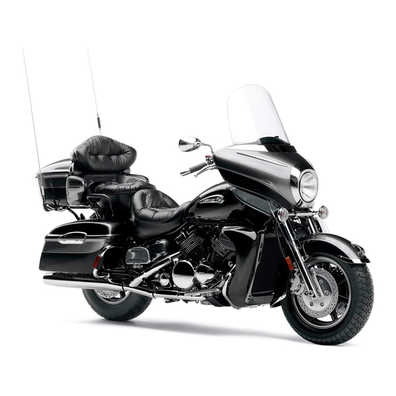
- Page 12 DESCRIPTION Right view 13. Muffler 21. Front fork air valve (page 3-19) 14. Tool kit (page 7-1) 22. Headlight (page 7-32) 15. Helmet holder (page 3-16) 23. Front turn signal lights (Page 7-33) 16. Travel trunk (page 3-18) 24. Fuse box A (page 7-31) 17.
- Page 13 DESCRIPTION Controls/Instruments 1. Clutch lever (page 3-10) 6. Main switch/steering lock (page 3-1) 2. Audio system control unit (page 4-3) 7. Right handlebar switches (page 3-10) 3. Left handlebar switches (page 3-9) 8. Throttle grip (page 7-18) 4. Rider headset jack (page 4-2) 9.
-
Page 14: Instrument And Control Functions
INSTRUMENT AND CONTROL FUNCTIONS Main switch/steering lock ........3-1 Fuel ..............3-13 Indicator lights ............3-3 Fuel tank breather hose ........3-13 Speedometer ............3-5 Fuel cock............3-14 Cruise control system ...........3-7 Starter (choke) knob .......... 3-15 Antitheft alarm (optional) ........3-8 Rider seat............3-15 Fuel gauge............3-9 Helmet holders ........... -
Page 15: Main Switch/Steering Lock
I NSTRUMENT AND CONTROL FUNCTIONS EAU00027 EAU01842 ACC (Accessory) The audio system, auxiliary DC termi- nal and jack can be used in this posi- tion. The key cannot be removed in this po- sition. Do not use the accessory posi- tion for an extended period of time as the battery may discharge. - Page 16 INSTRUMENT AND CONTROL FUNCTIONS EAU01861 (Parking) The steering is locked in this position, and the taillight, license light and auxil- iary light come on but all other circuits are off. The key can be removed in this position. To use the parking position, first lock the steering, then turn the key to “...
-
Page 17: Indicator Lights
If the indicator light does not come on left or right. while pushing the start switch, have a Yamaha dealer inspect the electrical EAU00063 2. High beam indicator light “ ” circuit. - Page 18 See page 3-7 for an explanation of the In such a case, take the motorcycle to a functions of these indicator lights. Yamaha dealer to have the self-diag- nostic systems checked. EAU00061 8. Neutral indicator light “...
-
Page 19: Speedometer
INSTRUMENT AND CONTROL FUNCTIONS Odometer and trip meter modes Resetting a meter Use the trip meters to estimate how far To reset a trip odometer to 0.0, select it you can ride on a tank of fuel. by pushing the “SELECT” button and Use the fuel reserve trip meter to see push the “RESET”... - Page 20 INSTRUMENT AND CONTROL FUNCTIONS Clock mode NOTE: After setting the clock, be sure to push To change the display to the clock the “SELECT” button before turning the mode, push the “SELECT” button for at main switch to “OFF”, otherwise the least two seconds.
-
Page 21: Cruise Control System
INSTRUMENT AND CONTROL FUNCTIONS 1. “CRUISE” switch 1. Cruise control switch 1. “SET” indicator light 2. “CANCEL” switch 2. “RES” indicator light EAU01776 3. “ON” indicator light Cruise control system 1. Push the “CRUISE” switch to the This motorcycle is equipped with a left to turn on the cruise control NOTE: cruise control system designed to... -
Page 22: Antitheft Alarm (Optional)
An antitheft alarm can be equipped to eling speed returns to within 8 km/h of trol. The traveling speed will return to this motorcycle. Consult your Yamaha the set speed. the previously set speed. The “RES” in- dealer to obtain and install the alarm. -
Page 23: Fuel Gauge
” for the low beam. diagnosis system. If there is a problem in an electric circuit, first the segments and then either “E” or “F” flash. In this case, be sure to consult a Yamaha dealer as soon as possible. -
Page 24: Clutch Lever
INSTRUMENT AND CONTROL FUNCTIONS EAU01859 7. Cruise control switches See page 3-7 for operation procedures. EAU00143 8. Start switch “ ” The starter motor cranks the engine when pushing the start switch. EC000005 CAUTION: 1. Clutch lever See starting instructions prior to EAU00138 EAU00152 starting the engine. -
Page 25: Shift Pedal
INSTRUMENT AND CONTROL FUNCTIONS 1. Shift pedal 1. Front brake lever 1. Rear brake pedal EAU01215 EAU00158 EAU00162 Shift pedal Front brake lever Rear brake pedal The shift pedal is located on the left The front brake lever is located on the The rear brake pedal is on the right side of the engine and is used in com- right handlebar. -
Page 26: Fuel Tank Cap
INSTRUMENT AND CONTROL FUNCTIONS NOTE: This tank cap cannot be closed unless the key is in the lock. The key cannot be removed if the cap is not locked properly. EW000023 WARNING Be sure the cap is properly installed and locked in place before riding the 1. -
Page 27: Fuel
INSTRUMENT AND CONTROL FUNCTIONS EAU00185 CAUTION: Always wipe off spilled fuel immedi- ately with a dry and clean soft cloth. Fuel may deteriorate painted surfac- es or plastic parts. EAU00191 Recommended fuel: 1. Filler tube 1. Fuel tank breather hose Regular unleaded gasoline with a 2. -
Page 28: Fuel Cock
INSTRUMENT AND CONTROL FUNCTIONS OFF: closed position ON: normal position RES: reserve position EAU02969 Fuel cock With the fuel cock in this position, fuel This indicates reserve. If you run out of The fuel cock supplies fuel from the flows to the carburetors. Set the fuel fuel while riding, set the fuel cock to this tank to the carburetors while filtering it cock to this position when starting the... -
Page 29: Starter (Choke) Knob
INSTRUMENT AND CONTROL FUNCTIONS 1. Starter (choke) knob 1. Nut ( 2) 1. Projection 2. Seat holder EAU03032 EAU01781 Starter (choke) knob Rider seat To install Starting a cold engine requires a richer To remove Insert the projection on the rear of the air-fuel mixture, which is supplied by Remove the nuts and lift up the rider rider seat into the seat holder, then... -
Page 30: Helmet Holders
INSTRUMENT AND CONTROL FUNCTIONS 1. Helmet holder (right) 1. Helmet holder (left) 2. Open 2. Open EAU01782 EWA00015 Helmet holders WARNING To open a helmet holder, insert the key Never ride with a helmet in either in the lock and turn it as shown. To lock helmet holder. -
Page 31: Saddlebags And Travel Trunk
INSTRUMENT AND CONTROL FUNCTIONS EAU01866 Never ride above 120 km/h with Saddlebags and travel trunk travel trunk and/or saddlebags EWA00021 because handling could be af- WARNING fected. This maximum speed Always be sure to close and may be reduced by such factors lock the saddlebags and travel as improper loading, poor tire trunk securely before operating... - Page 32 INSTRUMENT AND CONTROL FUNCTIONS 1. Storage compartment 1. Travel trunk lock 1. Lid resting in opened position 2. Storage pouch 2. Open 2. Storage pouch Travel trunk 2. Lift up the lid so that it will rest in To open place as shown when it is re- 1.
-
Page 33: Front Fork Adjustment
INSTRUMENT AND CONTROL FUNCTIONS EAU01878* Front fork adjustment This front fork is equipped with a spring preload adjuster. EW000035 WARNING Always adjust each fork leg to the same setting. Uneven adjustment can cause poor handling and loss of stability. To lock Adjust spring preload as follows. - Page 34 INSTRUMENT AND CONTROL FUNCTIONS Spring preload (air pressure): Minimum/Standard: 0 kPa (0 kg/cm , 0 bar) Maximum: 50 kPa (0.5 kg/cm , 0.5 bar) EC000012 CAUTION: Never exceed the maximum pres- 1. Front fork air valve cap sure, or oil seal damage may occur. 2.
-
Page 35: Rear Shock Absorber Adjustment
2. Remove the valve cap. low and if there is any indication of a 4. Install the valve cap securely. malfunction, return the motorcycle to a Yamaha dealer immediately for repair. 3-21... -
Page 36: Sidestand/Clutch Switch Operation Check
CD-11E WARNING TURN THE MAIN SWITCH TO “ON” If improper operation is noted, con- AND THE ENGINE STOP SWITCH TO sult a Yamaha dealer immediately. “ ”. TRANSMISSION IS IN GEAR AND SIDESTAND IS UP. PULL IN CLUTCH LEVER AND PUSH THE START SWITCH. -
Page 37: Auxiliary Dc Jack And Terminal
INSTRUMENT AND CONTROL FUNCTIONS 1. Auxiliary DC jack 1. Auxiliary DC terminal If accessories are used in excess of the EAU01788 Auxiliary DC jack and terminal specified consumption limit or with the This motorcycle is equipped with two engine turned off, the battery may dis- 12 V DC auxiliary outlets: a jack in the charge. -
Page 38: Audio System
AUDIO SYSTEM Location of parts ................4-1 Headsets (optional) ................4-2 Control unit..................4-3 Making basic settings................. 4-4 Making mode settings ................ 4-5 Cassette deck operation..............4-8 Radio operation................4-12 CD changer (optional) operation ............4-16 Auxiliary audio source operation ............4-17... -
Page 39: Location Of Parts
A UDIO SYSTEM EAU02933* Location of parts 1. Audio system control unit 5. Main switch/steering lock 1. Rear speaker ( 2) 2. Front speaker ( 2) 6. Eject (“ ”) button 2. Passenger volume control knob 3. Rider headset jack 7. -
Page 40: Audio System
For intercom use, two headsets are a long period of time when the that the headsets are selected as the necessary. Consult a Yamaha dealer if engine is not running as the bat- output. (See page 4-5 for instructions.) you wish to obtain headsets. -
Page 41: Control Unit
AUDIO SYSTEM Selecting a track on the optional Short push (less than 1 second) CD changer Turning on the audio system Tuning in a radio station manually Changing the audio source in the Adjusting the intercom volume following sequence Changing the settings in a mode (Tape) Long push (1 second or more) (Auxiliary... -
Page 42: Making Basic Settings
AUDIO SYSTEM Short push (less than 2 seconds) Changing modes in the following sequence BASS TREB SP/HS (Output) (Treble) (Fade ) Radio (Auto (Intercom frequency volume) volume) This mode does not appear in the display when the headsets are selected as the output. Making basic settings Adjusting the audio system volume This mode appears in the display only when one... -
Page 43: Making Mode Settings
AUDIO SYSTEM Making mode settings 3. While the selected mode is dis- played (for about 5 seconds), re- General procedure peatedly push either side of the The following setting procedure applies up/down switch for less than to the audio system and optional CD 1 second until the desired setting changer. - Page 44 AUDIO SYSTEM Adjusting the bass level Adjusting the treble level 1. Repeatedly push the “SELECT” 1. Repeatedly push the “SELECT” button for less than 1 second until button for less than 1 second until “BASS” appears at the bottom of “TREB”...
- Page 45 AUDIO SYSTEM NOTE: When the fade level is set to “0”, the front and rear speaker levels are the same. Adjusting the fade level (balance be- Adjusting the intercom volume tween front and rear speakers) 1. Repeatedly push the “SELECT” 1.
-
Page 46: Cassette Deck Operation
AUDIO SYSTEM Intercom operation Provided both the rider and passenger are wearing headsets, they can talk to each other through the intercom at any time. See page 4-7 for instructions on how to adjust the intercom volume. 1. Cassette deck compartment 2. - Page 47 AUDIO SYSTEM To clean the tape head, use a de-magnetizing cleaning cas- sette, but be sure to turn the volume all the way down to avoid speaker damage. Playing a cassette tape CAUTION: 1. Make sure that the audio system is Keep the cassette deck lid turned on.
- Page 48 AUDIO SYSTEM NOTE: The maximum number of songs that can be skipped in either direc- tion is 9. To stop skipping songs, push the up/down switch in the opposite di- rection that songs are being skipped. Skipping songs Skipping a blank While a cassette tape is playing, push When there is a long blank portion of either side of the up/down switch once...
- Page 49 AUDIO SYSTEM 1. Eject (“ ”) button Changing the tape play direction Turning on/off the Dolby noise re- Ejecting the cassette tape While the cassette tape is playing, duction system Push the eject (“ ”) button to eject the push either side of the up/down switch While the cassette tape is playing, tape from the cassette deck.
-
Page 50: Radio Operation
AUDIO SYSTEM 1. Radio antenna 1. Sleeve 1. Frequency band Radio operation Selecting a frequency band NOTE: This radio offers 3 FM bands and 1 AM The antenna can be folded down WARNING band. Since all 3 FM bands cover the after lifting the sleeve. - Page 51 AUDIO SYSTEM 3. Push either side of the up/down switch for less than 1 second until the desired frequency is dis- played. The frequency changes in 0.2-MHz steps for FM and in 10-kHz steps for AM. Tuning in a radio station automati- Tuning in a radio station manually cally In order to tune in a particular radio sta-...
- Page 52 AUDIO SYSTEM 3. Repeatedly push either side of the up/down switch for less than 1 second until the desired preset number (“1” through “6”) is dis- played. NOTE: Selecting “A” will automatically pro- gram the preset stations. See the fol- lowing section.
- Page 53 AUDIO SYSTEM 3. Push either side of the up/down switch once for 1 second or more to tune in a station automatically. 4. Repeatedly push either side of the up/down switch for less than 1 second until the desired preset number (“1”...
-
Page 54: Cd Changer (Optional) Operation
CD ap- mounted in the travel trunk. Ask a 2. Push the “AUDIO” button until pears in the display. Yamaha dealer to install the genuine “ ” as well as the CD number Clarion CDC635 model. -
Page 55: Auxiliary Audio Source Operation
AUDIO SYSTEM 1. Auxiliary audio input jack Auxiliary audio source 2. Repeatedly push the “AUDIO” but- ton for less than 1 second until operation “AUX” appears in the display. The Auxiliary audio equipment can be con- auxiliary equipment can now be nected to, and played through, the au- played through the audio system. -
Page 56: Pre-Operation Checks
PRE-OPERATION CHECKS Pre-operation check list..............5-1... -
Page 57: Pre-Operation Check List
P RE-OPERATION CHECKS EAU01114 Owners are personally responsible for their vehicle’s condition. Your motorcycle’s vital functions can start to deteriorate quickly and unexpectedly, even if it remains unused (for instance, if it is exposed to the elements). Any damage, fluid leak or loss of tire pressure could have serious consequences. - Page 58 PRE-OPERATION CHECKS ITEM CHECKS PAGE • Make sure that all nuts, bolts and screws are properly tightened. Chassis fasteners — • Tighten if necessary. • Check fuel level. Fuel 3-12 ~ 3-13 • Fill with fuel if necessary. Lights, signals and •...
-
Page 60: Operation And Important Riding Points
OPERATION AND IMPORTANT RIDING POINTS Starting the engine................6-1 Starting a warm engine ..............6-3 Shifting ....................6-3 Recommended shift points (for Switzerland only) ......6-4 Tips for reducing fuel consumption ............ 6-4 Engine break-in .................. 6-4 Parking ....................6-5... -
Page 61: Starting The Engine
Consult EW000054 corner. Yamaha dealer regarding any WARNING control or function that you do Before going through the following not thoroughly understand. steps, check the function of the sid- Never start your engine or let it estand switch and clutch switch. -
Page 62: Operation And Important Riding Points
If the engine trouble indicator light re- mains on, have a Yamaha dealer check the self-diagnosis system. 6. After starting the engine, move the 1. Turn the fuel cock to “ON”. -
Page 63: Starting A Warm Engine
OPERATION AND IMPORTANT RIDING POINTS EAU01258 EC000048 Starting a warm engine CAUTION: The starter (choke) is not required Do not coast for long periods when the engine is warm. with the engine off, and do not EC000046 tow the motorcycle a long dis- CAUTION: tance. -
Page 64: Recommended Shift Points (For Switzerland Only)
OPERATION AND IMPORTANT RIDING POINTS EAU02941 EAU00424 EAU01128 Recommended shift points Tips for reducing fuel Engine break-in (for Switzerland only) consumption There is never a more important period in the life of your motorcycle than the The recommended shift points are Your motorcycle’s fuel consumption period between zero and 1,600 km. -
Page 65: Parking
1,600 km and beyond Proceed with normal riding. EC000049 CAUTION: If any engine trouble should occur during the break-in period, consult a Yamaha dealer immediately. EAU01171 EAU00457 0 ~ 1,000 km Parking Avoid operation above 1/3 throttle. When parking the motorcycle, stop the engine and remove the ignition key. -
Page 66: Periodic Maintenance And Minor Repair
PERIODIC MAINTENANCE AND MINOR REPAIR Tool kit..............7-1 Front brake lever free play adjustment ....7-23 Periodic maintenance and lubrication....7-3 Rear brake pedal height adjustment ....7-23 Cowling and panel removal and installation..7-6 Brake light switch adjustment......7-24 Cowling A..............7-6 Checking the front and rear brake pads ..... 7-25 Cowling B..............7-7 Inspecting the brake fluid level ...... -
Page 67: Tool Kit
EW000060 WARNING If you are not familiar with motor- cycle service, this work should be done by a Yamaha dealer. 1. Owner’s tool kit EAU00464 EAU01844 Periodic inspection, adjustment and lu- Tool kit... - Page 68 PERIODIC MAINTENANCE AND MINOR REPAIR NOTE: If you do not have necessary tools re- quired during a service operation, take your motorcycle to a Yamaha dealer for service. EW000063 WARNING Modifications to this motorcycle not approved by Yamaha may cause loss of performance, and render it unsafe for use.
-
Page 69: Periodic Maintenance And Lubrication
PERIODIC MAINTENANCE AND MINOR REPAIR EAU00473 PERIODIC MAINTENANCE AND LUBRICATION CP-01E EVERY 6,000 km 12,000 km INITIAL ITEM CHECKS AND MAINTENANCE JOBS (1,000 km) 6 months 12 months (whichever (whichever comes first) comes first) • Check fuel hoses and vacuum hose for cracks or damage. Fuel line •... - Page 70 PERIODIC MAINTENANCE AND MINOR REPAIR EVERY 6,000 km 12,000 km INITIAL ITEM CHECKS AND MAINTENANCE JOBS (1,000 km) 6 months 12 months (whichever (whichever comes first) comes first) • Check bearing for looseness or damage. Wheel bearings • Replace if necessary. •...
- Page 71 Final gear oil • Change oil at initial 1,000 km and thereafter every 24,000 km or 24 months (whichever comes first). * Since these items require special tools, data and technical skills, they should be serviced by a Yamaha dealer. EAU02971 NOTE: The air filter needs more frequent service if you are riding in unusually wet or dusty areas.
-
Page 72: Cowling And Panel Removal And Installation
PERIODIC MAINTENANCE AND MINOR REPAIR EAU01139 Cowling and panel removal and installation The cowlings and panels illustrated need to be removed to perform some of the maintenance described in this chapter. Refer to this section each time a cowling or panel has to be removed or reinstalled. -
Page 73: Cowling B
PERIODIC MAINTENANCE AND MINOR REPAIR 1. Projection 1. Cowling B 1. Screw 2. Cowling A 2. Screw ( 2) To install To install EAU01794 1. Place the cowling in the original Cowling B 1. Place the cowling in the original position. -
Page 74: Panel C
PERIODIC MAINTENANCE AND MINOR REPAIR 1. Panel C 1. Panel D 2. Screw 2. Screw To install EAU00488 EAU00488 Place the panel in the original position Panel C Panel D and install the screw. To remove To remove Remove the screw and pull outward on Remove the screw and pull outward on the areas shown. -
Page 75: Panel E
PERIODIC MAINTENANCE AND MINOR REPAIR 1. Panel E 2. Screw To install To install 3. Bolt ( 2) Place the panel in the original position 1. Place the panel in the original po- EAU01795 and install the screw. sition and install the screw. Panel E 2. -
Page 76: Spark Plug Inspection
When installing a spark plug, the gas- lems yourself. Instead, take the motor- ket surface should always be cleaned cycle to a Yamaha dealer. The spark and a new gasket used. Any grime plugs should be periodically removed should be wiped off from the threads... -
Page 77: Engine Oil
PERIODIC MAINTENANCE AND MINOR REPAIR EAU01703 Engine oil Oil level inspection 1. Place the motorcycle on a level place and hold it in an upright posi- tion. Warm up the engine for seve- ral minutes. NOTE: Be sure the motorcycle is positioned 1. - Page 78 NOTE: filter wrench. An oil filter wrench is available at a nearby Yamaha dealer. NOTE: When installing the oil filter, tighten it to 5. Reinstall the drain bolt and tighten the proper torque by using a torque it to the specified torque.
-
Page 79: Final Gear Oil
EC000066 mains on, immediately stop the en- Yamaha dealer for repairs. CAUTION: gine and consult with a Yamaha Do not put in any chemical addi- dealer. tives. Engine oil also lubricates the clutch and additives could cause clutch slippage. -
Page 80: Coolant
Hard water or salt water is harmful to the engine. You may use distilled water if you can’t get soft water. NOTE: If water is added, have a Yamaha dealer check the antifreeze con- 1. Reservoir tank 1. Coolant reservoir tank cap tent of the coolant as soon as pos- 2. -
Page 81: Air Filters
PERIODIC MAINTENANCE AND MINOR REPAIR 1. Air filter case 1. Carburetor intake joint clamp screw 1. Air filter case bolt ( 5) For each air filter: 3. Remove the air filter case cover by EAU01877* Air filters 2. Loosen the carburetor intake joint removing the bolts. - Page 82 PERIODIC MAINTENANCE AND MINOR REPAIR 1. Air filter element 1. Air filter case drain hose 2. Air filter element screw ( 2) 5. Tap the air filter lightly to remove 6. Fit the projection on the air filter el- 4. Remove the air filter element by most of the dust and dirt and blow ement into the holder in the air fil- removing the screws.
-
Page 83: Carburetor Adjustment
A diagnostic tachometer must be used cated adjustment. Most adjustments for this procedure. should be left to a Yamaha dealer who 1. Attach the tachometer. Start the has the professional knowledge and engine and warm it up for a few experience to do so. -
Page 84: Throttle Cable Free Play Inspection
Yamaha service technician. a. Free play EAU00635 Throttle cable free play inspection There should be a free play of 4 ~ 6 mm at the throttle grip. If the free play is incorrect, ask a Yamaha dealer to make this adjustment. 7-18... -
Page 85: Tires
PERIODIC MAINTENANCE AND MINOR REPAIR EWA00018 EW000083 WARNING WARNING Tire inflation pressure should be Proper loading of your motorcycle checked and adjusted when the is important for several characteris- temperature of the tire equals the tics of your motorcycle, such as ambient air temperature. - Page 86 Yamaha dealer immediately. Brakes, tires, and relat- ed wheel parts replacement should 1. Side wall be left to a Yamaha Service Techni- a. Tread depth cian. Tire inspection CE-26E Always check the tires before operating Minimum tire tread depth 1.6 mm...
-
Page 87: Wheels
Tire valve PVR59A dling characteristics and short- by Yamaha Motor Co., Ltd. for this Valve core #9000 ened tire life. model. No guarantee for handling Ride at moderate speeds after... -
Page 88: Clutch Lever Free Play Adjustment
Ask a Yamaha dealer to do this service. 7-22... -
Page 89: Front Brake Lever Free Play Adjustment
The free play at the front brake lever positioned 100 mm above the top of Yamaha dealer inspect and should be 2 ~ 5 mm. the footrest. If not, ask a Yamaha deal- bleed the system if necessary. 1. Loosen the locknut. er to adjust it. -
Page 90: Brake Light Switch Adjustment
Air in the system will should be made by a Yamaha dealer. cause greatly diminished braking capability and can result in loss of control and an accident. Have a Yamaha dealer inspect and bleed the system if necessary. -
Page 91: Checking The Front And Rear Brake Pads
If the groove has almost disap- Before riding, check that the brake fluid allow checking of brake pad wear with- peared, ask a Yamaha dealer to re- is above the minimum level and fill out disassembling the brake. Inspect place the pads. -
Page 92: Brake Fluid Replacement
Clutch Brake fluid replacement The brake fluid should be replaced only by trained Yamaha service personnel. Have the Yamaha dealer replace the following components during periodic maintenance or when they are dam- aged or leaking: oil seals (every two years) 1. -
Page 93: Brake And Shift Pedal Lubrication
PERIODIC MAINTENANCE AND MINOR REPAIR EAU02984 EAU02985 Brake and shift pedal Brake and clutch lever lubrication lubrication Lubricate the pivoting parts. Lubricate the pivoting parts. Recommended lubricant: Recommended lubricant: Engine oil Engine oil 7-27... -
Page 94: Sidestand Lubrication
Recommended lubricant: fork rebounds smoothly. Engine oil EC000098 CAUTION: EW000113 If any damage or unsmooth move- WARNING ment is found with the front fork, If the sidestand does not move consult a Yamaha dealer. smoothly, consult a Yamaha dealer. 7-28... -
Page 95: Steering Inspection
If the battery seems to have dis- move them forward and backward. If charged, consult a Yamaha deal- any free play can be felt, ask a Yamaha dealer to inspect and adjust the steer- If the motorcycle is equipped with ing. - Page 96 If you do not have a sealed- Batteries produce explosive gases. type battery charger, contact Keep sparks, flame, cigarettes etc., your Yamaha dealer. away. Ventilate when charging or Always make sure the connec- using in an enclosed space. Always...
-
Page 97: Fuse Replacement
Install a new fuse of proper amperage. Turn on the switches and see if the electrical device operates. If the fuse immediately blows again, con- sult a Yamaha dealer. 1. Cruise control fuse 1. Ignition fuse EC000103 2. Carburetor heater fuse 2. -
Page 98: Headlight Bulb Replacement
PERIODIC MAINTENANCE AND MINOR REPAIR 1. Main fuse 1. Bulb holder cover 1. Bulb holder 2. Spare fuse 2. Headlight connector 2. Turn the bulb holder counterclock- Main fuse box EAU01802 wise to remove it and remove the Headlight bulb replacement The main fuse box is located behind defective bulb. -
Page 99: Turn Signal And Tail/Brake Light Bulb Replacement
Do not over-tighten the screws as a cloth moistened with alcohol or the lens may break. lacquer thinner. 4. Install the bulb holder cover and connect the headlight connector. If the headlight beam adjustment is necessary, ask a Yamaha dealer to make that adjustment. 7-33... -
Page 100: License Light Bulb Replacement
License light bulb If your motorcycle requires any repair, removing the nuts. replacement bring it to a Yamaha dealer. The skilled 3. Pull out the defective bulb. 1. Remove the license light assem- technicians at a Yamaha dealership 4. Install a new bulb. -
Page 101: Troubleshooting Charts
Remove spark plugs and check electrodes. Engine doesn’t start, go to battery Dry. Ask a Yamaha dealer to inspect. check. 4. Battery Engine turns over Battery good. quickly. Engine doesn’t start, ask a Yamaha Use the electric starter. - Page 102 Restart the engine. If the engine overheats again, ask a Level is OK. Yamaha dealer to inspect and repair the cooling system. NOTE: If it is difficult to get the recommended coolant, tap water can be temporarily used, provided that it is changed to the recom- mended coolant as soon as possible.
-
Page 104: Motorcycle Care And Storage
MOTORCYCLE CARE AND STORAGE Care ....................8-1 Storage....................8-4... - Page 105 M OTORCYCLE CARE AND STORAGE EAU01845 Before cleaning Cleaning 1. Cover up the muffler outlets with After normal use plastic bags. Remove dirt with warm water, a neutral 2. Make sure that all caps and covers detergent and a soft clean sponge, as well as all electrical couplers then rinse with plenty of clean water.
- Page 106 MOTORCYCLE CARE AND STORAGE ECA00036 Do not use any harsh chemical For motorcycles equipped with CAUTION: products on plastic parts. Be a windshield: Do not use strong Avoid using strong acidic wheel sure to avoid using cloths or cleaners or hard sponges as cleaners, especially on spoked sponges which have been in they...
- Page 107 MOTORCYCLE CARE AND STORAGE After riding in the rain, near the sea or After cleaning EWA00001 WARNING on salt-sprayed roads 1. Dry the motorcycle with a chamois Make sure that there is no oil or wax Since sea salt or salt sprayed on the or an absorbing cloth.
- Page 108 NOTE: Always store your motorcycle in a cool, “OFF” position: Turn the fuel cock Consult a Yamaha dealer for advice on dry place and, if necessary, protect it to “OFF”. what products to use.
- Page 109 MOTORCYCLE CARE AND STORAGE a. Remove the spark plug caps and 6. Lubricate all control cables and 9. Remove the battery and fully spark plugs. the pivoting points of all levers and charge it. Store it in a cool, dry b.
-
Page 110: Specifications
SPECIFICATIONS Specifications ..................9-1 HOW TO USE THE CONVERSION TABLE ........9-5... - Page 111 S PECIFICATIONS EAU01038 Specifications Model XVZ1300TF Engine oil Dimensions Type -20˚ -10˚ 0˚ 10˚ 20˚ 30˚ 40˚ 50˚C Overall length 2,705 mm SAE 10W/30 Overall width 900 mm SAE 10W/40 Overall height 1,565 mm (except for D) SAE 15W/40 1,380 mm (for D)
- Page 112 SPECIFICATIONS Final gear oil Operation Left foot operation Type SAE80API “GL-4” Hypoid Gear Gear ratio 2.529 Quantity 0.2 L 1.632 Cooling system capacity 1.200 (total amount) 3.5 L 0.960 Air filter Dry type element 0.786 Fuel Chassis Type Regular unleaded gasoline Frame type Double cradle Fuel tank capacity...
- Page 113 SPECIFICATIONS Maximum load* 190 kg Rear Air pressure (cold tire) Type Single disc brake Up to 90 kg load* Operation Right foot operation Front 250 kPa (2.50 kg/cm , 2.50 bar) Fluid DOT 4 Rear 250 kPa (2.50 kg/cm , 2.50 bar) Suspension 90 kg load ~ maximum Front...
- Page 114 SPECIFICATIONS Headlight type Quartz bulb (halogen) Audio system amplifier Bulb voltage, wattage quantity Output power Headlight 12 V, 60/55 W Speaker 14 W Tail/brake light 12 V, 5/21 W Headset Turn signal light 12 V, 21 W Auto-volume range 5 steps Auxiliary light 12 V, 4 W Output impedance...
-
Page 115: How To Use The Conversion Table
SPECIFICATIONS EAU01064 HOW TO USE THE CONVERSION TABLE CS-02E CONVERSION TABLE All specification data in this manual are listed in SI and METRIC TO IMPERIAL METRIC UNITS. Metric unit Multiplier Imperial unit Use this table to convert METRIC unit data to IMPERIAL m·kg 7.233 ft·lb... -
Page 116: Consumer Information
CONSUMER INFORMATION Identification number records............10-1 Key identification number ..............10-1 Vehicle identification number............10-1 Model label..................10-2... -
Page 117: Identification Number Records
Record the key identification number, vehicle identification number and mod- el label information in the spaces pro- vided for assistance when ordering spare parts from a Yamaha dealer or for reference in case the vehicle is sto- len. 1. Key identification number 1. -
Page 118: Consumer Information
The model label is affixed to the frame under the rider seat. (See page 3-15 for rider seat removal and installation pro- cedures.) Record the information on this label in the space provided. This information will be needed to order spare parts from your Yamaha dealer. 10-2... -
Page 119: Left View
I NDEX 1 1 - Start switch........3-10 Turn signal switch .......3-9 Air filters..........7-15 Dimmer switch......... 3-9 Headlight bulb replacement....7-32 Antitheft alarm (optional) ......3-8 Headsets (optional) ........4-2 Auxiliary audio source operation ....4-17 Engine break-in ........6-4 Helmet holders........3-16 Auxiliary DC jack and terminal ....3-23 Engine oil .......... -
Page 120: Right View
INDEX Making mode settings......4-5 Sidestand/clutch switch operation Model label ..........10-2 check ..........3-22 Sidestand lubrication......7-28 Spark plug inspection......7-10 Neutral indicator light ....... 3-4 Specifications.......... 9-1 Speedometer .......... 3-5 Oil level indicator light......3-3 Starter (choke) knob......3-15 Overdrive indicator light ...... - Page 121 PRINTED ON RECYCLED PAPER YAMAHA MOTOR CO., LTD. 5JC-28199-E1 PRINTED IN JAPAN 99 · 9 - 0.3...
Need help?
Do you have a question about the Venture XVZ1300TF and is the answer not in the manual?
Questions and answers