Table of Contents
Advertisement
Chapter 1
Overview
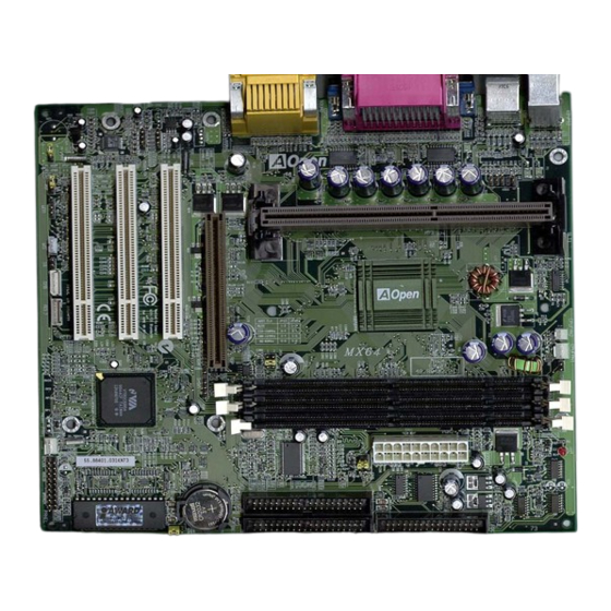
MX64 is a slot 1 based motherboard that utilizes VIA 694X AGPset on Micro
ATX form factor. It implements an onboard audio CODEC and supports new
architectures such as AGP 4x, SDRAM, Ultra DMA 33/66, Bus master IDE
and USB ports. It supports three Dual in-line memory module (DIMM) slots
that allow the installation of SDRAM memory and expansion up to a maximum
of 768MB.
In addition to the above features, MX64 also implements plenty of fabulous
features.
Jumper-less Design Pentium II / Pentium III / Celeron VID signal and SMbus
clock generator provide CPU voltage auto-detection and allows the user to set
the CPU frequency through the CMOS setup, therefore no jumpers or switches
are used. The correct CPU information is saved into the EEPROM. With these
technologies, the disadvantages of the Pentium based jumper-less designs
are eliminated. There will be no worry of wrong CPU voltage detection and no
need to re-open the housing in case of CMOS battery loss. The only jumper
left is to clear the CMOS, which is a safety hook if you forget the password.
Full-range CPU core voltage This motherboard supports the CPU core
voltage from 1.3V to 3.5V, that can be applied to various CPU type in future.
Zero Voltage Wake on Modem In conjunction with ATX soft power On/Off, it
is possible to have system totally power off and wakeup to automatically
answer a phone call such as answering machine or to send/receive fax. The
most important break through is not only external box modem but also internal
modem card can be used to support 0V Wake On Modem. The MX64 and
FM56-P internal modem card implement special circuit (patent applied) to
make sure the modem card work properly without any power.
Wake on LAN This feature is very similar as 0V Wake On Modem, but it is
through local area network. To use Wake on LAN function, you must have a
network card that supports this feature and also need to install a network
management software.
1-1
Advertisement
Table of Contents

Related Manuals for AOpen MX64


Summary of Contents for AOpen MX64
- Page 1 Chapter 1 Overview MX64 is a slot 1 based motherboard that utilizes VIA 694X AGPset on Micro ATX form factor. It implements an onboard audio CODEC and supports new architectures such as AGP 4x, SDRAM, Ultra DMA 33/66, Bus master IDE and USB ports.
- Page 2 Resetable Fuse MX64 implements resetable fuses to prevent any accidental short circuit caused by keyboard or USB devices hot plug. FCC DoC Certificate MX64 has passed FCC DoC test. The radiation is very low, you can use any kind of housing.
-
Page 3: Specifications
Overview Specifications Micro ATX Form Factor 220 mm x 245 mm Board Size Intel Pentium II / Pentium III / Celeron System Memory DIMM 168-pin x3, maximum 768MB. Built-in CPU depends on processor Second-level Cache VIA 694X AGPset Chipset Expansion Slots PCI x 3 and AGP x 1 Audio CODEC AD1881... -
Page 4: Zero Voltage Wake On Modem
0V Wake On Modem, but if you use external modem, you have to keep the box modem always power-on. AOpen MX64 and internal modem card implement special circuit (patent applied) and make sure the modem card works properly without any power. - Page 5 Overview For Internal Modem Card (AOpen FM56-P): 1. Go into BIOS setup, Power Management 0V Wake On Modem, select Enabled. 2. Setup your application, put into Windows 95. 3. Turn system power off by soft power switch. 4. Connect 4-pin Modem Ring-On cable from FM56-P RING connector to MX64 connector WKUP.
-
Page 6: System Voltage Monitoring
Overview System Voltage Monitoring This motherboard implements a voltage monitoring system. As you turn on your system, this smart design will continue to monitor your system working voltage. If any of the system voltage is over the component's standard. There will be alarm through application software such as Hardware Monitor utility for a warning to user. -
Page 7: Cpu Thermal Protection
Overview CPU Thermal Protection This motherboard implements special thermal protection circuit below the CPU. When temperature is higher than a predefined value, the CPU speed will automatically slow down and there will be warning from BIOS and also Hardware Monitoring Utility software. CPU Thermal Protection is automatically implemented by BIOS and utility software, no extra hardware installation is needed. -
Page 8: Hardware Installation
Chapter 2 Hardware Installation This chapter gives you a step-by-step procedure on how to install your system. Follow each section accordingly. Caution: Electrostatic discharge (ESD) can damage your processor, disk drives, expansion boards, and other components. Always observe the following precautions before you install a system component. -
Page 9: Jumper And Connector Locations
Hardware Installation 2.1 Jumper and Connector Locations The following figure shows the locations of the jumpers and connectors on the system board: CD-IN2 JP12 CD-IN MODEM-CN COM2 COM1 PRINTER INSPK JP27 PS/2 MS USB2 AOL2 CPUFAN2 JP29 CPU FAN1 IrDA DIMM1 DIMM2 DIMM3... - Page 10 Hardware Installation Jumpers: JP12: Sound JP14: Clear CMOS JP27: PC Beep JP23, JP29: Host CLK Connectors: PS2: PS/2 mouse connector PS/2 keyboard connector COM1: COM1 connector COM2: COM2 connector PRINTER: Printer connector PWR2: ATX power connector USB: USB connector (port 1, 2) USB2: USB second connector (port 3, 4) FDC:...
-
Page 11: Selecting The Cpu Frequency
Hardware Installation 2.2 Jumpers With the help of the Pentium II Pentium III / Celeron VID signal and SMbus, this motherboard is a jumper-less design. 2.2.1 Selecting the CPU Frequency The Pentium II \ Pentium III \ Celeron VID signal and the SMbus clock generator provide CPU voltage auto-detection and allow the user to set CPU frequency through the CMOS setup, no jumpers or switches are needed. -
Page 12: Setting The Cpu Voltage
Hardware Installation Intel Celeron CPU Core Frequency Ratio FSB Clock Celeron 266 266MHz= 66MHz Celeron 300 300MHz= 4.5x 66MHz Celeron 300A 300MHz= 4.5x 66MHz Celeron 333 333MHz= 66MHz Celeron 366 366MHz= 5.5x 66MHz Celeron 400 400MHz= 66MHz Celeron 433 433MHz= 6.5x 66MHz Celeron 466... - Page 13 Hardware Installation The procedure to clear CMOS: 1. Turn off the system and unplug the AC power. 2. Remove ATX power cable from connector PWR2. 3. Locate JP14 and short pins 2-3 for a few seconds. 4. Return JP14 to its normal setting by shorting pins 1-2. 5.
- Page 14 Hardware Installation 100-124 MHz 66-83 MHz (2X) (3X)
-
Page 15: On Board Audio
Hardware Installation Mode CPU (Host) Memory 133/100/66 3X, overclocking 149/112/74.6 33 66.5 133/100 4X, overclocking 77.5 37.5 2.2.5 On Board Audio JP12 On Board Audio If you want to install another sound card, it is necessary to disable the onboard audio Enabled (default) by setting this jumper to Disabled. -
Page 16: Power Cable
Hardware Installation 2.3 Connectors 2.3.1 Power Cable The ATX power supply uses a 20-pin connector as shown below. Make sure you plug in the cable in the right direction. Caution: Make sure that the power supply is off before connecting or disconnecting the power cable. -
Page 17: Serial Devices (Com1/Com2)
Hardware Installation 2.3.3 PS/2 Mouse The onboard PS/2 mouse connector is a 6-pin Mini-Din connector marked PS2. The view angle of drawing shown here is from the back panel of the housing. PS/2 Mouse 2.3.4 Keyboard The onboard PS/2 keyboard connector is a 6-pin Mini-Din connector marked KB2. -
Page 18: Usb Device
Hardware Installation 2.3.6 Printer The onboard printer connector is a 25-pin D-type connector marked PRINTER. The view angle of the drawing shown here is from the back panel of the housing. PRINTER 2.3.7 USB Device You can attach USB devices to the USB connector. The motherboard contains two USB connectors, which are marked as USB. -
Page 19: Ide Hard Disk And Cd Rom
Hardware Installation 2.3.9 IDE Hard Disk and CD ROM This motherboard supports two 40-pin IDE connectors marked as IDE1 and IDE2. IDE1 is also known as the primary channel and IDE2 as the secondary channel. Each channel supports two IDE devices that make a total of four devices. -
Page 20: Panel Connector
Hardware Installation 2.3.10 Panel Connector The Panel (multifunction) connector is a 20-pin connector marked as PANEL SPWR on the board. Attach the power LED, KEYLOCK keylock, speaker, SPWR, IDE LED and ACPI & POWER LED reset switch to the corresponding pins IDE LED as shown in the figure. - Page 21 Hardware Installation Description Install the infrared module onto the IrDA connector enable infrared function from the BIOS setup, make sure to have the correct orientation when you IRRX plug in the IrDA connector. IRTX IrDA 2-14...
-
Page 22: Wake On Modem Connector
Internal Modem card consumes no power when system RING power is off, it is recommended to use an internal modem. To use AOpen MP56, connect 4-pin cable from RING connector of MP56 to the WOM connector on the motherboard. 2.3.13 Wake on LAN Connector Description This motherboard implements a WOL connector. -
Page 23: Configuring The System Memory
Hardware Installation 2.4 Configuring the System Memory The DIMM type supported is SDRAM (Synchronous DRAM), Registered SDRAM and Virtual Channel Memory. This motherboard has three 168-pin DIMM sockets (Dual-in-line Memory Module) that allow you to install system PIN1 memory up to 768MB. Warning: This motherboard does not support EDO DRAM. - Page 24 Hardware Installation Caution: Some SDRAMs marked as -10 may work fine with 100 MHz CPU clock, but not all of this kind of modules can work properly under 100MHz external clock. We suggest you choose and install SDRAMs that match PC 100 specification if 100MHz or above CPU clock is selected.
- Page 25 Hardware Installation Total Memory Size = Size of DIMM1 + Size of DIMM2 + Size of DIMM3 The following table list the recommended SDRAM combinations of DIMM: DIMM Bit size Single/ Chip DIMM size Recommended Data chip per side Double side count 1M by 16 1Mx64...
-
Page 26: Software Installation
Chapter 4 Software Installation This chapter gives you a step-by-step procedure on how to install the driver and utility of this motherboard. Because chipset and technology improvement is faster than operating system, sometimes we need certain procedures to successfully install necessary software. Please follow each section accordingly. You can use the autorun menu of Bonus CD Disc. - Page 27 Software Installation 4.1 Software Installation in Windows 95 For installing Windows 95, please make sure you have followed below procedures. First, don’t install any add-on card. Install Window 95 into your system. Install Windows 95 OSR2 v2.1, 1212 or 1214 version and later with USB support.
- Page 28 Software Installation 4.2 Software Installation in Windows 98 For installing Windows 98, please make sure you have followed below procedures. First, don’t install any add-on card. Enable USB Controller in BIOS Setup menu to make BIOS fully capable of controlling IRQ assignment. Install Window 98 into your system.
-
Page 29: Via 4 In 1 Driver
Software Installation 4.3 VIA 4 in 1 Driver You can install the VIA 4 in 1 ( IDE Busmaster, VIA AGP, IRQ Routing Driver, VIA Registry ) from the Bonus Pack CD disc autorun menu. - Page 30 When VIA 4 in 1 driver was installed, choose to reboot your system. When the system restarts, the Audio device will be automatically detected. Give the correct path from the AOpen Bonus Pack Disc ( driver path can refer to readme.txt under the motherboard directory ).
- Page 31 Hardware Monitoring Utility, no hardware installation is needed. Hardware Monitoring Utility (the program’s file name is like aohwxxx.exe, where xxx means the version number) is developed by AOpen which monitors the status of system voltage, thermal, & fan. This utility is especially designed for personal user.
- Page 32 Software Installation 4.6 Install Norton AntiVirus You can install this antivirus software from AOpen Bonus Pack CD disc, please follow the procedure below. To install Norton Antivirus, please follow the procedure below. To run AOchip, please follow the procedure below.
- Page 33 Software Installation...
- Page 34 Software Installation 4.7 Install Docucom Reader The AOpen Bonus Pack CD disc includes an online manual of this motherboard, which is PDF file format. You must use Docucom Reader to read these PDF files. To install Docucom Reader, please follow the procedure below.
-
Page 35: Award Bios
Chapter 3 Award BIOS This chapter tells how to configure the system parameters. You may update your BIOS via AWARD Flash Utility. Important: Because the BIOS code is the most often changed part of the motherboard design, the BIOS information contained in this chapter (especially the Chipset Setup parameters) may be a little different compared to the actual BIOS that... -
Page 36: Entering The Award Bios Setup Menu
AWARD BIOS Entering the Award BIOS Setup Menu The BIOS setup utility is a segment of codes/routines residing in the BIOS Flash ROM. This routine allows you to configure the system parameters and save the configuration into the 128 byte CMOS area, (normally in the RTC chip or directly in the main chipset).
Need help?
Do you have a question about the MX64 and is the answer not in the manual?
Questions and answers