Table of Contents
Advertisement
Advertisement
Table of Contents

Related Manuals for Jensen MS30


Summary of Contents for Jensen MS30
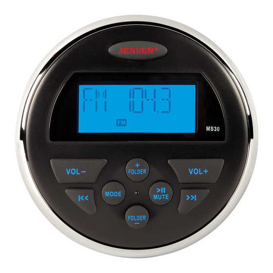
- Page 1 MS30 Owner’s Manual MS30 VOL- VOL+ FOLDER >ll MODE MUTE >>l l<< FOLDER...
-
Page 2: Table Of Contents
MS30 CONTENTS Introduction ........................ 1 Features ..........................1 Box Contents......................... 1 Compliance ........................... 1 Safety Information ......................... 2 Installation ........................3 Mounting the Radio ....................... 3 Auxiliary Input........................4 Line Output..........................4 Wiring Diagram ........................5 Operation ........................6 Basic Functions........................6 Audio Menu ........................... -
Page 3: Introduction
MS30 INTRODUCTION Thank you for choosing a Jensen product. We hope you will find the instructions in this owner’s manual clear and easy to follow. If you take a few minutes to look through it, you’ll learn how to use all the features of your new Jensen receiver for maximum enjoyment. -
Page 4: Safety Information
MS30 Safety Information • To ensure full satisfaction with the product, please read the entire instruction manual. • Keep instructions for future reference. • Follow all operation guidelines and adhere to all safety warnings and cautions to ensure safe use. -
Page 5: Installation
MS30 INSTALLATION Mounting the Radio Choose a mounting location on the dash board or instrument panel that will allow room behind to run radio cables to the power source. Consider how you will use the AUX IN, LINE OUT and USB connectors and route the appropriate extension cables to an accessible area. -
Page 6: Auxiliary Input
MS30 Auxiliary Input Connect a portable audio device to the Audio Input (AUX IN RIGHT/LEFT) on the back of the unit using RCA cables. Line Output The Line Out connectors (LINE OUT RIGHT/LEFT) on the back of the unit output a line-level... -
Page 7: Wiring Diagram
MS30 Wiring Diagram USB Connector Black ANTENNA Black AUX IN RIGHT (red) Yellow AUX IN LEFT (white) 10AMP Yellow Type ATO Fuse LINE OUT RIGHT (red) Grey LINE OUT LEFT (white) Grey NOTE: Do not connect the red wire to a constant power connection. -
Page 8: Operation
FOLDER Basic Functions Power Press the JENSEN power button (1) to turn the unit on/off. Restore Factory Settings Perform the following steps to reset the radio to factory default settings: Press and hold the power button (1) to display the software version. -
Page 9: Audio Menu
With the display showing the current tuning mode, press the VOL - or VOL+ button (2, 3) to change between USA/EURO. Press the JENSEN power button (1) to confirm your selection. Frequency Tuning Press the l<< or >>l button (6, 7) to fine tune the radio frequency. -
Page 10: Usb Mode
MS30 USB Mode Insert/Remove USB Device You can connect a USB device directly to the USB interface at the rear of the radio for playback of compatible files. Playback begins automatically. Press the MODE button (8) to switch to USB mode from another source. -
Page 11: Troubleshooting
MS30 TROUBLESHOOTING Table 1: Troubleshooting Problem Solution No Power If the power supply is connected to the vehicle accessory circuits but the engine is not on, switch the ignition key to “ACC” Fuse may be blown. Replace with 10 AMP ATO fuse. -
Page 12: Specifications
MS30 SPECIFICATIONS General Power Supply Requirements......DC 12 Volts, Negative Ground Operating Voltage ..........10-16VDC Unit Dimensions . - Page 13 ASA Electronics Corporation www.asaelectronics.com www.jensenheavyduty.com www.jensenmarinedirect.com/ ©2012 ASA Electronics Corporation v. 061812...
Need help?
Do you have a question about the MS30 and is the answer not in the manual?
Questions and answers