Table of Contents
Advertisement
This .pdf document is bookmarked
Operating Instructions and Parts Manual
8-in x 13-in Horizontal Cut-Off Bandsaw
Model: J-7015
WALTER MEIER (Manufacturing) Inc.
427 New Sanford Road
LaVergne, Tennessee 37086
Part No. M-414450
Ph.: 800-274-6848
Revision B 03/2012
www.waltermeier.com
Copyright © 2012 Walter Meier (Manufacturing) Inc.
Advertisement
Table of Contents

Related Manuals for Jet J-7015


Summary of Contents for Jet J-7015
- Page 1 This .pdf document is bookmarked Operating Instructions and Parts Manual 8-in x 13-in Horizontal Cut-Off Bandsaw Model: J-7015 WALTER MEIER (Manufacturing) Inc. 427 New Sanford Road LaVergne, Tennessee 37086 Part No. M-414450 Ph.: 800-274-6848 Revision B 03/2012 www.waltermeier.com Copyright © 2012 Walter Meier (Manufacturing) Inc.
-
Page 2: Warranty And Service
Walter Meier is consistently adding new products to the line. For complete, up-to-date product information, check with your local Walter Meier distributor, or visit waltermeier.com. WARRANTY JET products carry a limited warranty which varies in duration based upon the product (MW = Metalworking, WW = Woodworking). WHAT IS COVERED? This warranty covers any defects in workmanship or materials subject to the exceptions stated below. -
Page 3: Table Of Contents
Table of Contents Warranty and Service..........................2 Table of Contents ..........................3 Warnings............................4 Introduction ............................6 Specifications .............................6 Machine Features ..........................7 Unpacking and Assembly ........................8 Electrical Connection ..........................8 Controls and Indicators ........................9 Blade Selection ..........................10 Operations ............................10 Adjustments ............................. 14 Maintenance ............................ 18 Cleaning ............................ -
Page 4: Warnings
Warnings 1. Read and understand the entire owner's manual before attempting assembly or operation. 2. Read and understand the warnings posted on the machine and in this manual. Failure to comply with all of these warnings may cause serious injury. 3. - Page 5 21. Keep visitors a safe distance from the work area. Keep children away. 22. Make your workshop child proof with padlocks, master switches or by removing starter keys. 23. Give your work undivided attention. Looking around, carrying on a conversation and “horse-play” are careless acts that can result in serious injury.
-
Page 6: Introduction
The Model J-7015 Horizontal Cut-off Bandsaw is equipped with a coolant system that can greatly extend blade life and speed the cutting of a variety of materials that are best cut with cutting fluids and coolants. -
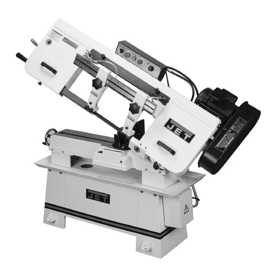
Page 7: Machine Features
The saw head (Figure 2) consists of a drive Figures 1 and 2 depict the main features of the motor, drive pulleys, gearbox, blade wheels, Model J-7015 Horizontal Cut-Off Bandsaw. The blade guides and supports, control panel, blade machine consists of a machine base onto which tension/blade tracking mechanism, wire brush, is installed a saw head. -
Page 8: Unpacking And Assembly
The mechanism also has adjustment screws Remove the saw from the shipping skid; discard that enable the saw blade to “track” evenly on any hold-down devices. Place the saw on the the blade wheels. The adjustment screws shop floor; secure the saw to the floor using change the angle of the driven blade wheel shaft mounting anchors secured through four holes in so the wheels are aligned. -
Page 9: Controls And Indicators
(clockwise adjustment) reduces the Note: Belt position A shown below feed rate. Blade Speeds The Model J-7015 horizontal cut-off bandsaw has four blade speeds. The different speeds are obtained by changing the position of the motor Figure 6 drive V-belt on step pulleys. Change blade speeds as follows: 6. -
Page 10: Blade Selection
However, the following procedure will be adequate for break-in of JET-supplied blades on lower alloy ferrous materials. 1. Clamp a section of round stock in the vise. The stock should be 2 inches or larger in diameter. - Page 11 Evaluating Cutting Efficiency Setting The Vise For Angle Cuts Is the blade cutting efficiently? The best way to Referring to Figure 9, the vise can be adjusted determine this is to observe the chips formed by through a 45-degree arc as follows: the cutting blade.
- Page 12 Starting the Saw Important: The efficient operation of the cut-off saw is dependent upon the condition of the saw blade. If the performance of the saw begins to deteriorate, the first item that you should check is the blade. Flats/Strips Rounds If a new blade does not restore the machine’s cutting accuracy and quality, refer to the...
- Page 13 The coolant pump must be The work stop is an accessory that is included submerged before operating to prevent with the JET J-7015 Bandsaw. It is used to set damage to the pump. up the saw for making multiple cuts of the same Adjust the coolant flow shut-off valve at the top length.
-
Page 14: Adjustments
Adjustments Blade Tracking Adjustment Refer to Figures 13 and 14. Blade tracking has been set and tested at the factory. Adjustment is rarely required when the blade is used properly or if the blade is correctly welded. If adjustment is needed: 1. -
Page 15: Blade Guide Adjustment
15. Close the wheel covers (K, Fig. 14). Blade Guide Adjustment Referring to Figure 15: The J-7015 Bandsaw has two adjustable blade guide assemblies, each consisting of the blade guide support or bracket (B, H)) and blade guide (A). The position of the blade guides is important in order to make accurate cuts and prolong blade life and is determined by the size of the workpiece. -
Page 16: Blade Guide Bearing Adjustment
Blade Guide Bearing Adjustment Referring to Figure 16: Guide bearings and guide inserts are located on either side of the saw blade and provide stability for the blade when the saw is in operation. These bearings rotate on an eccentric shaft so the distance from the blade can be adjusted for optimal performance. - Page 17 1. Clamp vise and mart top of bar stock here Verifying Adjustment Accuracy 2. Cut of a slice of Refer also to Figure 18. the bar stock Test cuts can be used to determine whether or not you have adjusted the blade accurately. Use 2 inch round bar stock to perform these test cuts, as 3.
-
Page 18: Maintenance
Maintenance Figure 21 Store the removed blade carefully before Changing Blades proceeding. 6. Slide the new blade into the blade guides Use leather gloves when (J), then loop the blade (G) around the drive changing the saw blade to protect your wheels (H) such that the teeth face towards hands from... - Page 19 Changing the Drive Belt Referring to Figures 22 and 23: Disconnect the cut-off saw from its electrical power source. 1. Set the arm at the full horizontal position. 2. Open the drive belt cover to expose the V-belt and pulleys . 3.
-
Page 20: Cleaning
Cleaning 1. Clean off any preservative on machine Upper Wheel Bushing – six to eight drops of oil surfaces. each week. After cleaning: Pivot Points, Shafts, and Bearing areas – six to eight drops of oil each week. 2. Coat machined surfaces of the cutoff saw with a medium consistency machine oil. -
Page 21: Troubleshooting
Troubleshooting Fault Probable Cause Suggested remedy 1. Material loose in vise. 1. Clamp work securely. 2. Incorrect speed or feed. 2. Check Machinist’s Handbook for speed/feed appropriate for the material being cut. 3. Teeth too coarse for material. 3. Check Machinist’s Handbook for recommended blade type. - Page 22 Troubleshooting Fault Probable Cause Suggested remedy 1. Blade speed too high for feed 1. Reduce blade speed and feed pressure. pressure. Bad cuts (rough) 2. Blade is too coarse. 2. Replace with finer blade. 1. Blade is binding in the cut. 1.
-
Page 23: Parts
7 ....7015-7 ....Pivot Shaft ..................1 8S.... 7015-8S ....Cylinder Assembly ................1 9 ....7015-9 ....Ext. Retaining Ring ...........S18......1 12 .... J-7015-12 ....Cylinder Upper Bracket ............... 1 13 .... TS-0720081 ....Lock Washer ............5/16" ......3 14 .... TS-1504061 ....Socket Head Cap Screw ........M8x30......3 15 .... - Page 24 39 .... TS-1524021 ....Socket Set Screw ..........M8x10......1 40 .... TS-1540061 ....Hex Nut............M8 ......1 41 .... TS-1490081 ....Hex Cap Screw ..........M8x45......1 42 .... J-7015-42 ....Front Moveable Vise Jaw ..............1 43 .... 7015-43....Bushing....................1 44 .... TS-1550071 ....Flat Washer............M10 ......1 45 ....
-
Page 25: Saw Stand And Bed - Parts Breakdown
Saw Stand and Bed – Parts Breakdown... -
Page 26: Saw Head
302-1 ..TS-1550031 ....Flat Washer............M5 ......6 302-2 ..TS-2245102 ....Button Head Socket Screw ........M5x10......6 303 ..J-7015-303 ....Left Blade Wheel Cover ..............1 304 ..TS-2361081 ....Lock Washer ............M8 ......4 305 ..TS-1540061 ....Hex Nut............M8 ......4 306 .. - Page 27 326 ..TS-1505021 ....Socket Head Cap Screw ........M10x20 ...... 3 327 ..TS-1551071 ....Lock Washer ............M10 ......3 328 ..J-7015-328 ....Gear Box Assembly ..........1:30 8mm ....1 329 ..TS-1540071 ....Hex Nut............M10 ......2 330 ..7015-330....Shaft ....................1 330-1 ..
- Page 28 357 ..7015-357....Tension Indicator ................1 358 ..7015-358....Lock Washer, Tension ........ID16.3x31.5x1.8t ..10 359 ..7015-359....Tension Shaft ..................1 360 ..J-7015-360 ....Tension Slide Base ................1 360-1 ..7015-360-1 ....Tension Scale ..................1 361 ..TS-1523051 ....Socket Set Screw ..........M6x16......1 362 ..
-
Page 29: Saw Head - Parts Breakdown
Saw Head – Parts Breakdown... -
Page 30: Electric Assembly - Parts And Breakdown
Electric Assembly – Parts and Breakdown Index No. Part No. Description Size 5-1 ..7015-5-1A ....Fuse Base .....VLC10 ....... 2 (serial no12040936 and higher) 5-3 ... 7015-5-3A ....Fuse ......KTK-2A ...... 1 (serial no12040936 and higher) 5-4 ..7015-5-4 ....Magnetic Contactor ...........SDE MA-15 ....1 5-5 ... -
Page 31: Wiring Diagram
Wiring Diagram... -
Page 32: Ordering Replacement Parts
Ordering Replacement Parts To order parts or reach our service department, call 1-800-274-6848 Monday through Friday (see our website for business hours, www.waltermeier.com). Having the Model Number and Serial Number of your machine available when you call will allow us to serve you quickly and accurately. WALTER MEIER (Manufacturing) Inc.
Need help?
Do you have a question about the J-7015 and is the answer not in the manual?
Questions and answers