Table of Contents
Advertisement
Quick Links
Advertisement
Table of Contents

Related Manuals for Jet J-9225


Summary of Contents for Jet J-9225
- Page 1 This .pdf document is bookmarked Operating Instructions and Parts Manual 8-3/4" Zip-Miter Bandsaw Model J-9225 427 New Sanford Road LaVergne, Tennessee 37086 Part No. M-414467 Ph.: 800-274-6848 Revision C 01/2016 www.jettools.com Copyright © 2014 JET...
-
Page 2: Warranty And Service
JET sells through distributors only. The specifications listed in JET printed materials and on official JET website are given as general information and are not binding. JET reserves the right to effect at any time, without prior notice, those alterations to parts, fittings, and accessory equipment which they may deem necessary for any reason ®... -
Page 3: Table Of Contents
Table of Contents Warranty and Service ..........................2 Table of Contents ............................ 3 Warning ..............................4 Introduction ............................. 6 Specifications ............................6 Shipping Contents ........................... 7 Contents of the Carton ......................... 7 Hardware ............................. -
Page 4: Warning
5. Do not use this bandsaw for other than its intended use. If used for other purposes, JET, disclaims any real or implied warranty and holds itself harmless from any injury that may result from that use. -
Page 5: Save These Instructions
20. Make your workshop child proof with padlocks, master switches or by removing starter keys. 21. Give your work undivided attention. Looking around, carrying on a conversation and “horse-play” are careless acts that can result in serious injury. 22. Maintain a balanced stance at all times so that you do not fall or lean against the blade or other moving parts. -
Page 6: Introduction
The Model J-9225 bandsaw is equipped with a coolant system which can greatly extend blade life and speed the cutting of a variety of materials which are best cut with cutting fluids and coolants. -
Page 7: Shipping Contents
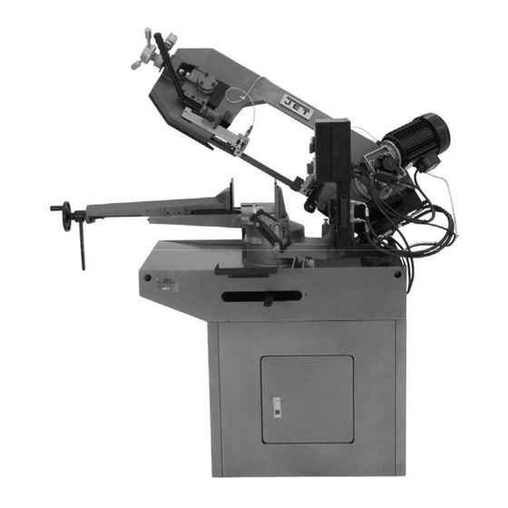
Figures 1 depicts the main features of the Model on the set rod to establish the length of the J-9225 Bandsaw. The machine consists of a workpiece and the stop rod can be adjusted to machine base onto which is installed a saw accommodate workpieces of various widths. -
Page 8: Assembly
Determine the final location for the saw and The Model J-9225 bandsaw is rated at 230V. allow for a sufficient work space around it. This machine is not supplied with a plug. Use a The saw is extremely heavy. -
Page 9: Controls And Indicators
On/Off Switch to ON, select Motor Speed Selector to Low or High, Emergency Stop must be released. Blade Speeds The Model J-9225 bandsaw has two blade speeds which are set by the Motor Speed Figure 4 Selector dial (D, Fig. 4). In normal operation the... -
Page 10: Blade Selection
Opening the needle valve stainless steel, tool steel, or titanium, call JET further increases the feed rate. for more specific blade recommendations. JET... -
Page 11: Setting The Work Stop
Setting the Work Stop Referring to Figure 5: The work stop is an accessory that is included with the JET J-9225 Bandsaw. It is used to set up the saw for making multiple cuts of the same length. Do not allow the blade to rest on the workpiece when the saw is not cutting. -
Page 12: Miter Cuts
Miter Cuts Referring to Figure 7, the J-9225 band saw is capable of making angle cuts from 0–60º. The vise remains stationary while the saw head is adjusted as follows: 1. Place the saw head (F) in the raised position so the blade doesn't catch in the table slots. -
Page 13: Bearing And Guide Block Adjustment
Bearing and Guide Block Adjustment Referring to Figure 10: Guide bearings and carbide guide blocks are located on either side of the saw blade and provide stability for the blade when the saw is in operation. These bearings rotate on an eccentric shaft so the distance from the blade can be adjusted for optimal performance. -
Page 14: Blade Tension
See Adjusting the proper Blade Tension on page 16. Limit Switch Adjustment Refer to Figure 12. The J-9225 bandsaw should shut off automatically when a cut is completed. If not, the limit switch probably needs to be adjusted as follows: Disconnect the cut-off saw from its electrical power source. -
Page 15: Maintenance
Maintenance Figure 13 Changing Blades 4. Pull the blade (E) off the drive wheel (F) and Refer to Figure 13 except where specified idler wheel (G) and out of the blade guides otherwise. ). Store the removed blade carefully before proceeding. Use leather gloves when Installing New Blade changing the saw blade to protect your... -
Page 16: Cleaning
Cleaning Coolant Clean off any preservative on machine surfaces. Change coolant on a frequency appropriate to the type of coolant being used. Oil based After cleaning: coolants can sour. Refer to the coolant supplier’s instructions for change frequency. 1. Coat machined surfaces of the cutoff saw with a medium consistency machine oil. -
Page 17: Troubleshooting
Troubleshooting Fault Probable Cause Suggested remedy 1. Material loose in vise. 1. Clamp work securely. 2. Incorrect speed or feed. 2. Check Machinist’s Handbook for speed/feed appropriate material being cut. 3. Teeth too coarse for material. 3. Check Machinist’s Handbook for recommended blade type. -
Page 18: Parts
Troubleshooting (cont.) Fault Probable Cause Suggested remedy 1. Blade speed too high for feed 1. Reduce blade speed and feed pressure. pressure. Bad cuts (rough) 2. Blade is too coarse. 2. Replace with finer blade. 1. Blade is binding in the cut. 1. -
Page 19: Saw Assembly - Parts
Saw Assembly – Parts Index No. Part No. Description Size 1 ....J-9225-01G ....Body Frame ................... 1 2 ....J-9225-02G ....Anchor Block ..................1 2A .... J-9225-02A ....Anchor Plate ..................1 2B .... TS-2245102 .....Button Head Socket Screw .........M5x10 ......2 3 .... - Page 20 Saw Assembly – Parts Index No. Part No. Description Size 73 ..... TS-2361061 .....Lock Washer ............M6 ......4 74GA ..9225-74GA ....Gear Box Assembly ................1 75 ..... TS-1551071 .....Lock Washer ............M10 ......4 76 ..... TS-1505021 .....Socket Head Cap Screw ........M10x20 ...... 4 77 .....
- Page 21 178 ... 9225-178 ....Washer...............ø6.5xø18x1.5 ..... 1 179 ... TS-1503041 .....Socket Head Cap Screw ........M6x16 ......1 180 ... J-9225-180G ....Front Moveable Vise Jaw............... 1 181 ... 9225-181 ....Vise Jaw Insert ..................1 182 ... TS-1514011 .....Flat Head Socket Screw ........M6x12 ......2 183 ...
- Page 22 250-1 ..J-9225-250-1G ..Rear Stand Panel .................. 1 250-2 ..J-9225-250-2G ..Right Stand Panel.................. 1 250-3 ..J-9225-250-3G ..Front Stand Panel with door (serial no 07080025 and higher) ....1 250-4 ..J-9225-250-4G ..Left Stand Panel with hook (serial no 07080025 and higher) ....1 250-5 ..
-
Page 23: Saw Assembly Drawing (1 Of 3)
Saw Assembly Drawing (1 of 3) - Page 24 Saw Assembly Drawing (2 of 3)
- Page 25 Saw Assembly Drawing (3 of 3)
-
Page 26: Electrical Box Assembly - Parts
215-9 ..9180-215-9 ....Fuse Lid ....................1 215-10 ..9180-215-10 ....Fuse ..............2A ......1 215-11 ..J-9180-215-11 ..Electrical Box Cover ................1 215-12 ..J-9225-215-12 ..Electrical Box..................1 215-13 ..9180-215-13 ....Cable Relief ................... 2 215-14 ..9180-215-14 ....Cable Relief ................... 1 215-15 .. -
Page 27: Electrical Box Assembly
Electrical Box Assembly... -
Page 28: Wiring Diagram
Wiring Diagram 427 New Sanford Road LaVergne, Tennessee 37086 Phone: 800-274-6848 www.jettools.com...
Need help?
Do you have a question about the J-9225 and is the answer not in the manual?
Questions and answers